Plate fin for heat exchanger and heat exchanger core

a heat exchanger and plate fin technology, applied in the direction of heat exhanger fins, tubular elements, stationary conduit assemblies, etc., can solve the problems of poor applicability of corrugated fins, inability to apply corrugated fins to heat exchangers (evaporators) for air conditioner indoor units, heat pump outdoor units or evaporators, and condensed water, etc., to achieve high reliability, high productivity for mass production, and reliable alignmen

Inactive Publication Date: 2006-09-26
T RAD CO LTD
View PDF10 Cites 13 Cited by
  • Summary
  • Abstract
  • Description
  • Claims
  • Application Information

AI Technical Summary

Benefits of technology

[0024]The plate fin for heat exchanger and the heat exchanger core according to the present invention are structured as described above, and have the following advantages.
[0026]Accordingly, since all fin elements are connected continuously with each other at the connected portion 1, each of the slits 3 can be reliably aligned with each other. Thus, the flat tubes 4 can be easily inserted into the slits 3. Thereby, a plate fin for heat exchanger with high reliability as well as high productivity for mass production can be obtained.
[0027]Moreover, in the plate fin, since the flat tubes 4 can be engaged with the aggregation 24 of fin elements at the front and rear sides thereof, so-called a double tube type heat exchanger can be structured. Thus, a compact plate fin with high heat exchange performance can be obtained.
[0028]In the above structure, the slits 3 neighboring in the longitudinal direction of the strip-shaped metal plate 18 can be disposed in a zigzag manner. Owing to this arrangement, the front side flat tube 4 and the rear side flat tube 4 in the aggregation 24 of fin elements can be disposed closer to each other. Thus, a compact heat exchanger with high performance can be provided.
[0029]In the above structure, one of the two sides 5 of the connected portion 1 is formed into a V-like shape; and another side is formed into an inversed V-like shape. The protruding portions of V-like shape may be bent into the bent portions 20. Owing to this arrangement, the connected portion 1 can easily specify the gap between the fin elements, and the entire connected portion 1 can be rigidly structured.
[0030]Further, the heat exchanger core employing the above-described plate fin can be manufactured easily and precisely.

Problems solved by technology

However, there reside such problems as drainage of condensed water, frost accumulation in heating operation and the like.
Therefore, the corrugated fins cannot be applied to heat exchangers (evaporators) for air conditioner indoor units, heat pump outdoor units or evaporators for refrigerators and automatic vending machines.
Thus, the corrugated fins may be evaluated to be poor in applicability.
That is, when incorporated into a heat exchanger, corrugated fins are remarkably poor in drainage performance due to the configuration thereof, and therefore frost gathers and grows swiftly; and further, the frost is hardly removed.
However, being different from the case where a tube having a circular section (round tube) is used, it is difficult to insert the flat tube into the flat hole.
When the enough clearance is provided, the contact between the tube and the fin is deteriorated, resulting in reduction of performance.
Being different from the case of the round tube, the flat tube cannot be satisfactorily expanded from the inside thereof.
However, when the clearance is formed large enough to ensure the insertion efficiency, brazing material is not satisfactorily supplied to the gap between the two; thus, the contact between the two is deteriorated, resulting in a reduction of the heat conductivity.
Contrarily, when the clearance is formed small enough to ensure satisfactory brazing, the insertion efficiency of the tube is lowered, resulting in an extreme reduction of the productivity.
In such a case, however, expansion process of the tube needs to be added, which leads to such disadvantages as redundant process, poor productivity and a big investment for equipment.
In this case, however, the tube is not allowed to be expanded.
However, the plate type heat exchanger with slit fins as described above has a following disadvantage.
That is, when the individual plate fins are gathered together and many slits are to be aligned, it is difficult to align them into a line properly and thus, handling is troublesome.
Therefore, the plate type heat exchanger has not been put into volume production.
However, it is difficult to align the slits in the plate fins and form a fin assembly practically.
Further, there arises such disadvantage that the core assembly has poor workability in engaging the tubes with the fins, since the slits are hardly aligned with each other.

Method used


Image

  • Plate fin for heat exchanger and heat exchanger core
  • Plate fin for heat exchanger and heat exchanger core
  • Plate fin for heat exchanger and heat exchanger core

Examples


Embodiment Construction

[0041]Now, an embodiment of the present invention will be described with reference to the drawings.

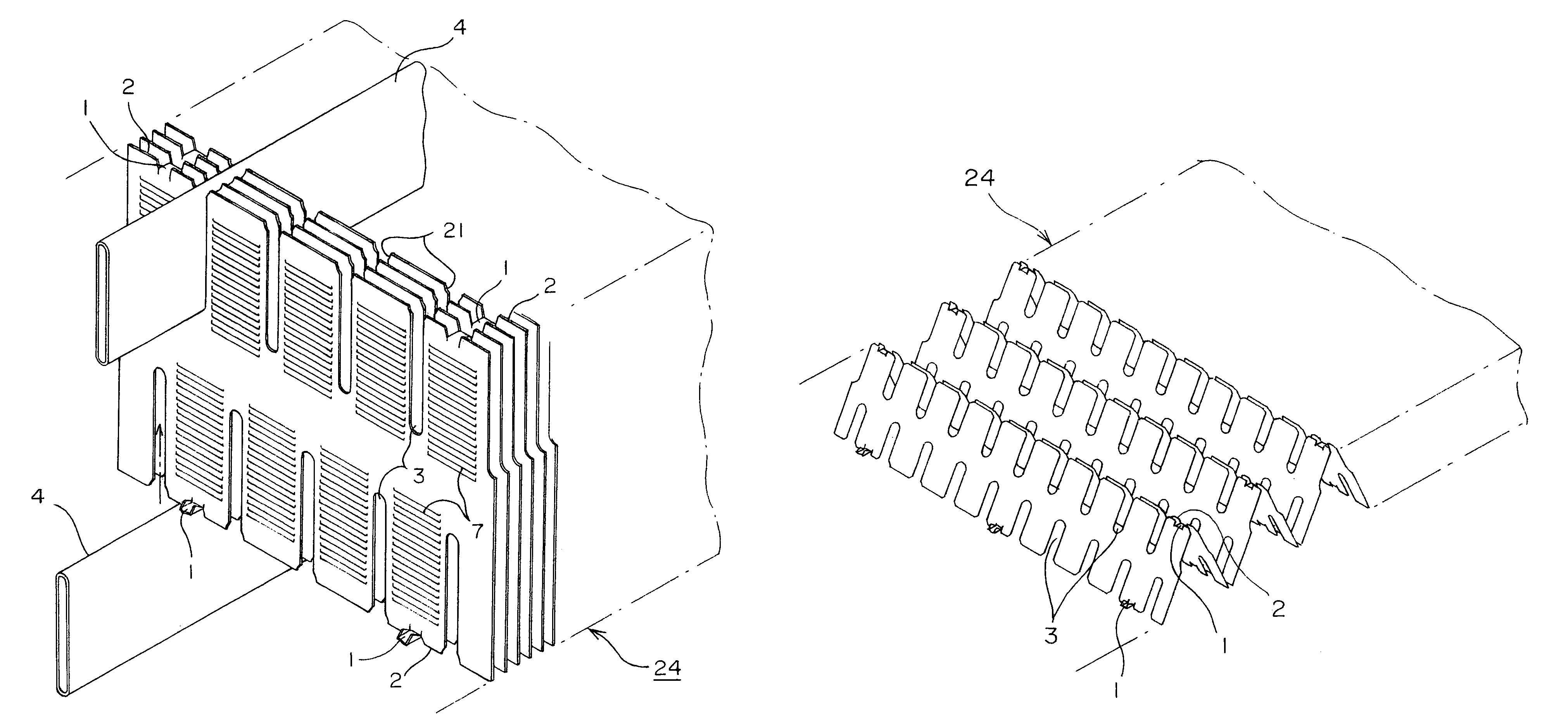
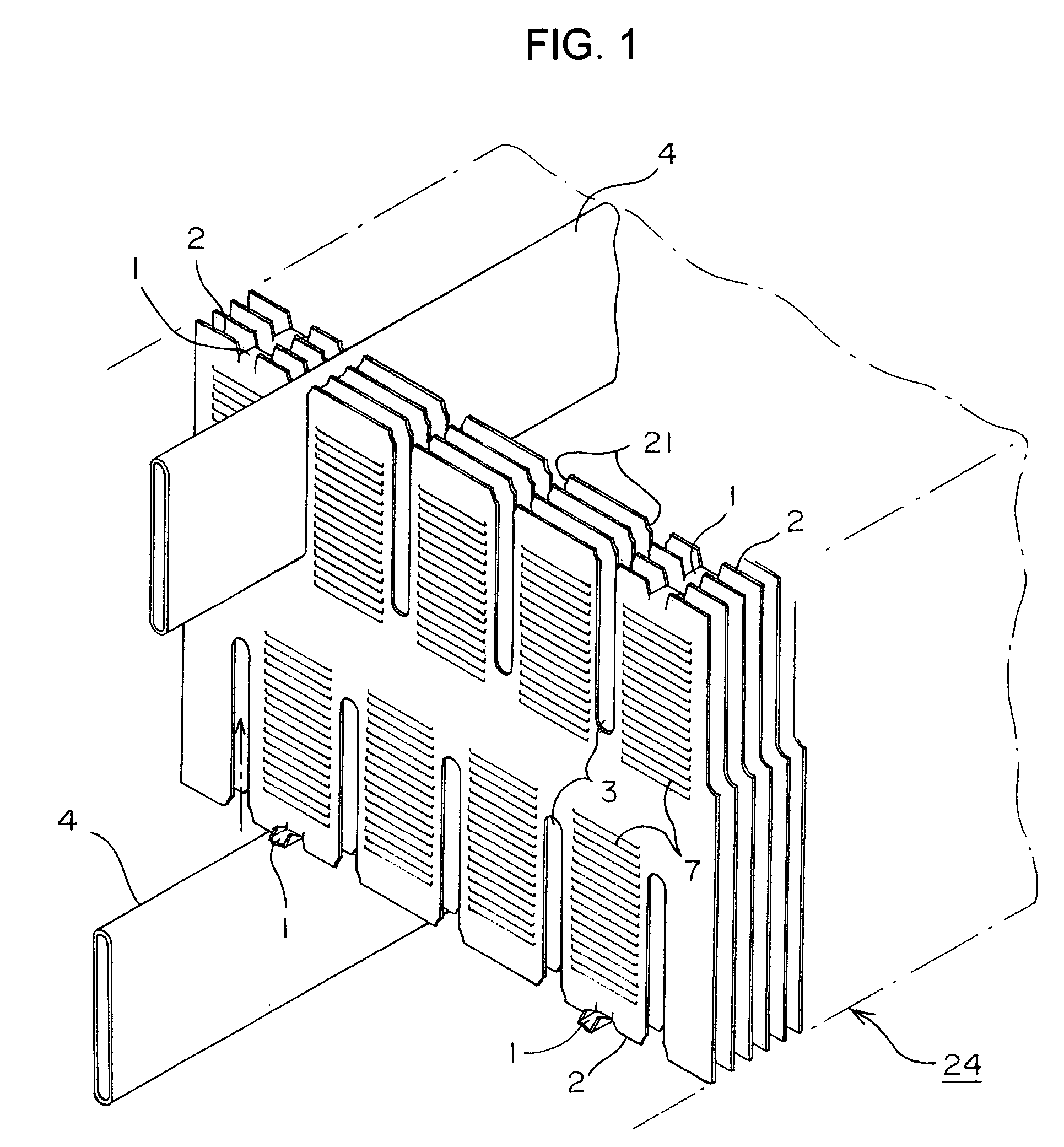
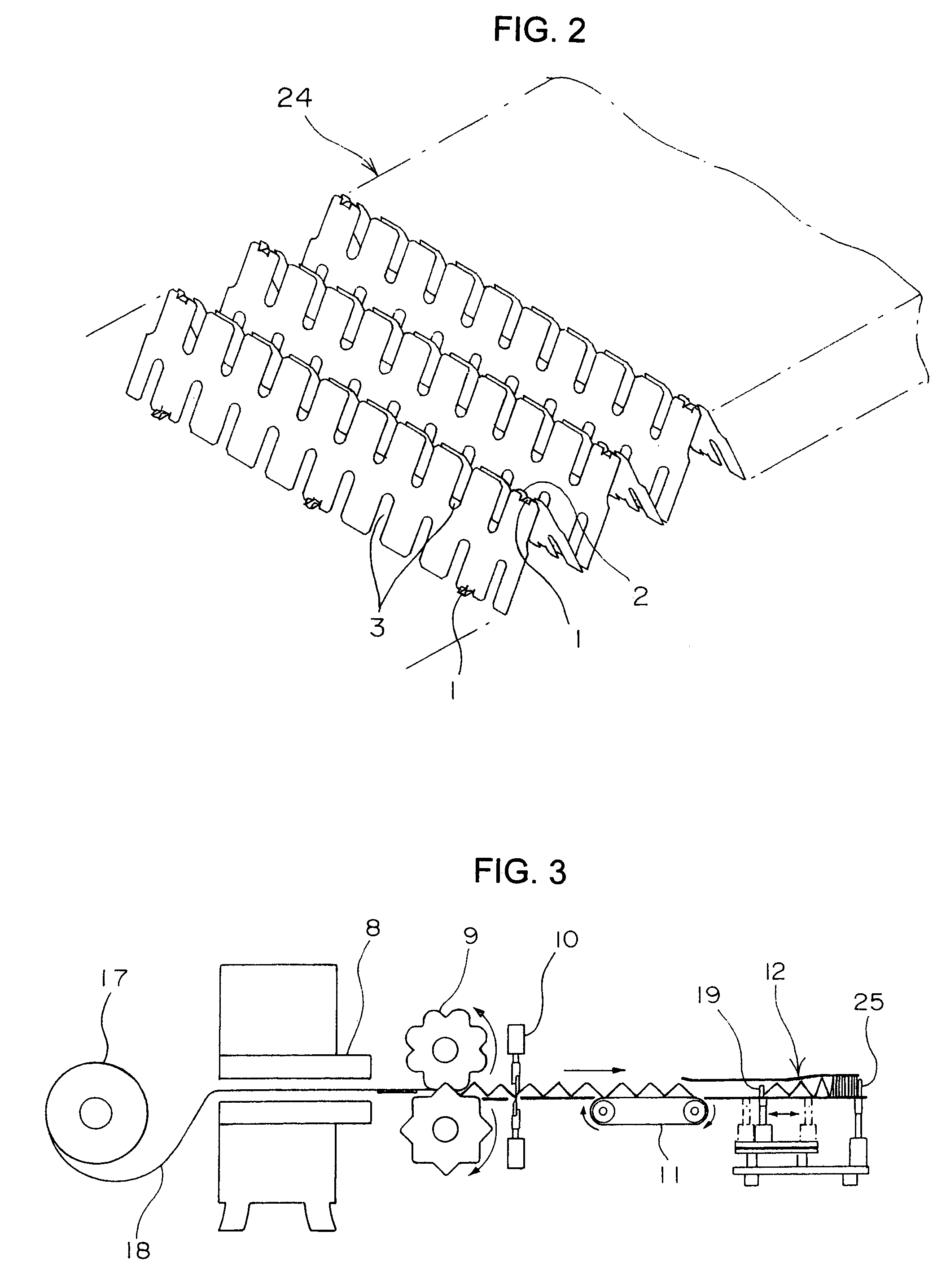
[0042]FIG. 1 is an exploded perspective view of an principal portion of a heat exchanger core in accordance with the present invention, FIG. 2 is an illustration showing a part of a plate fin thereof under manufacturing process, FIG. 3 is an illustration of the entire manufacturing process thereof, FIG. 4 is a plan view of an principal portion of a strip-shaped metal plate 18 under a press-forming process in FIG. 3, and FIG. 5 is an enlarged view of a portion V in FIG. 4. Further, FIG. 6 is a perspective view illustrating each connected portion 1 in aggregation 24 of the fin elements.

[0043]As shown in FIG. 1, the heat exchanger core is arranged so that a strip-shaped thin metal plate 18 is folded into a zigzag shape to form an aggregation 24 of fin elements. From the front side and the rear side in the thickness direction of the aggregation 24 of the fin elements, flat tubes 4 are enga...


PUM


Abstract

A plate type heat exchanger employing flat tubes, which can be manufactured easily and which have a high heat exchange performance includes a thin strip-shaped metal plate cut in the width direction and having remaining small connected portions and many cut portions disposed at fixed intervals in the longitudinal direction slits are formed in both sides of the cut potions having the same center. The strip-shaped metal plate is bent at the connected portions in a zigzag manner to form an aggregation of fin elements, and the flat tubes are engaged with the front and rear sides of the aggregation of the fin elements.

Description

TECHNICAL FIELD[0001]The present invention relates to a plate fin type heat exchanger that has flat tubes, and more particularly to a heat exchanger of a type in which flat tubes are pressed into slits on each plate fin.BACKGROUND ART[0002]Conventionally, fins applied to flat tubes that have been used generally in a radiator for automobile and a condenser for car air conditioner are corrugated fins.[0003]It seems that corrugated fins have almost reached to a saturated level technically and further contrivance to reduce air resistance significantly than the current level, to increase performance or to reduce weight is approaching to the limit.[0004]Corrugated fins are applicable to radiators for automobiles, condensers for car air conditioners and outdoor units of air conditioners. However, there reside such problems as drainage of condensed water, frost accumulation in heating operation and the like. Therefore, the corrugated fins cannot be applied to heat exchangers (evaporators) f...

Claims


Application Information

Patent Timeline
Patent Type & Authority Patents(United States)
IPC IPC(8): F28F1/22B21D53/08F28D1/053F28F1/32
CPCF28F1/128F28F1/325F28F2215/12F28D1/0478F28D1/05366F28F2275/04F28F2275/12
Inventor YOSHIOKA, JUNSASAKI, KIYOSHISATOH, JOHJI
Owner T RAD CO LTD
Why Eureka
Try Eureka