Turbofan arrangement
a technology for aircraft turbofans and arrangement parts, which is applied in the direction of rocket engine plants, machines/engines, engine manufacture, etc., can solve the problems of increasing the number of turbine stages, increasing the number of turbines, etc., to improve the design of known multiple fan engines, and increase the mean diameter or stage loading of turbines
- Summary
- Abstract
- Description
- Claims
- Application Information
AI Technical Summary
Benefits of technology
Problems solved by technology
Method used
Image
Examples
first embodiment
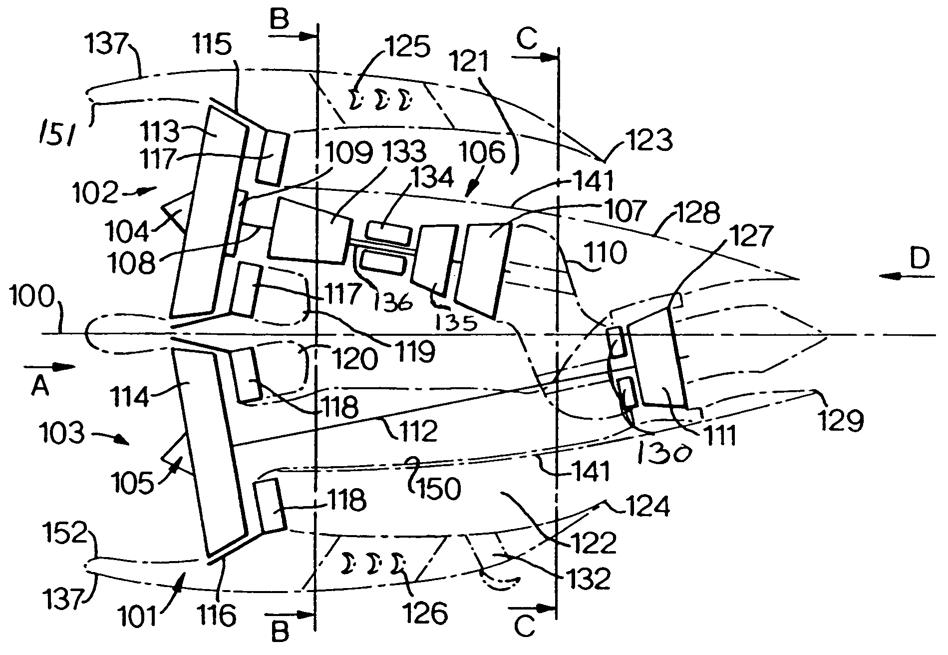
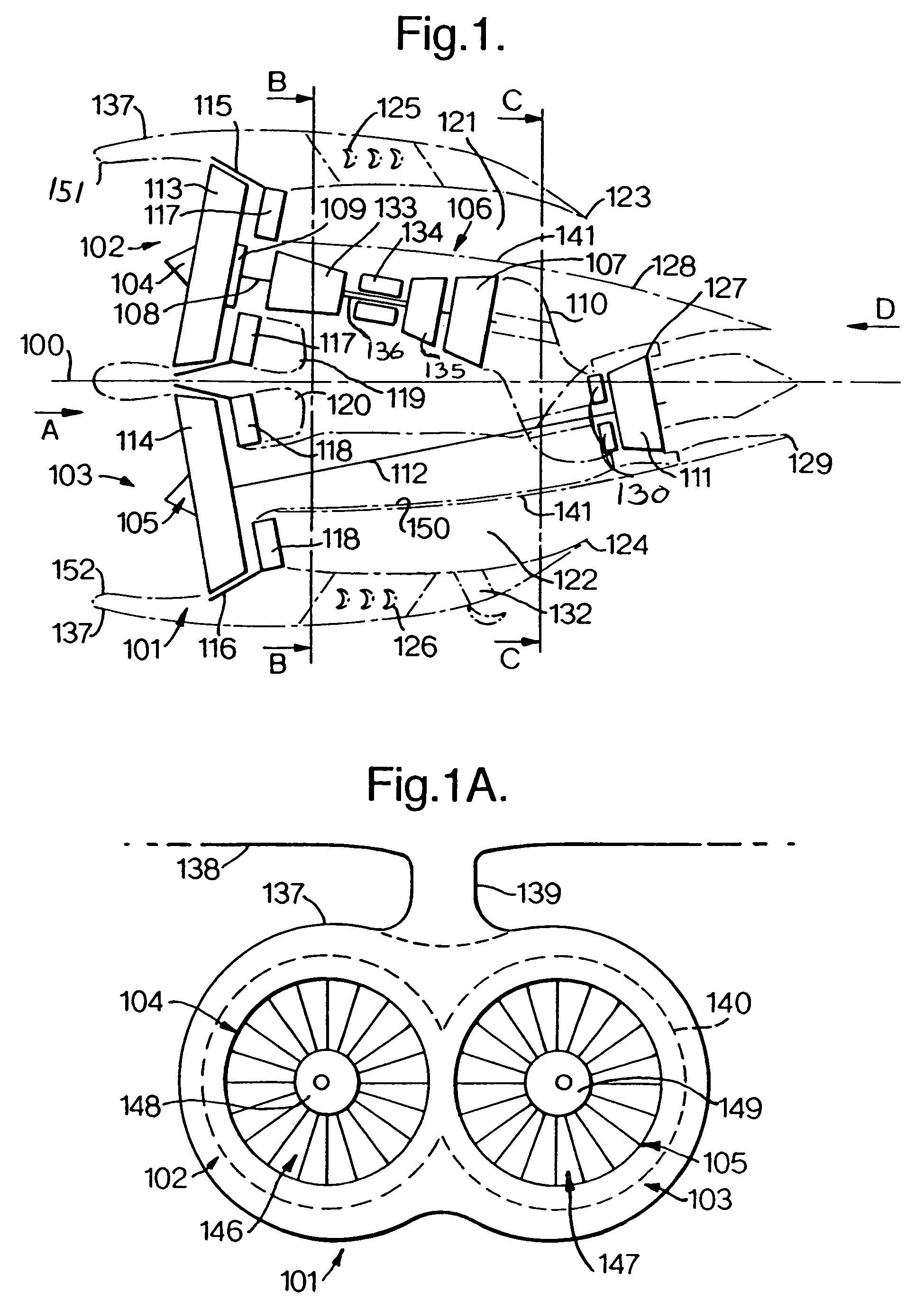
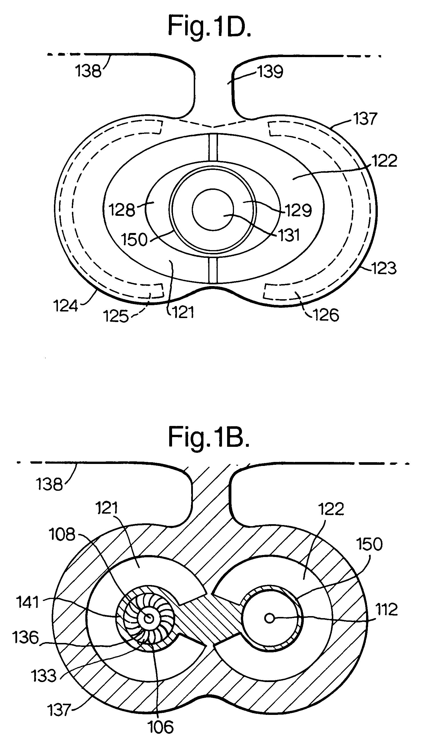
[0034]With reference to FIG. 1, the turbofan engine 101 is a low specific thrust engine 101 configured with first and second propulsion systems 102, 103 comprising first and second fan systems 104 and 105 respectively that are disposed equi-angularly about a centre-line 100. The first and second fan systems 104 and 105 each comprise a first and second fan rotor 113, 114 respectively and are mounted generally side by side, when installed on an aircraft wing that is generally horizontal, in an integrated nacelle 137. The nacelle 137 comprises two intake systems 151 and 152. The fan systems 104 and 105, in use, are co-rotating to maximise parts commonality. Alternatively, the fan systems 104 and 105 are arranged to contra-rotate, thereby minimising gyro-couples and maximising turbine efficiencies. The first fan system 104 has a conventional bypass ratio η1 and is followed, in the downstream flow direction, by a conventional core engine or gas generator 106 coaxial to the first fan syst...
second embodiment
[0059]FIG. 2 shows a turbofan engine 201, generally similar in configuration to the turbofan engine 101 described with reference to FIG. 1, except that synchronisation of the speeds of the fan rotors 113 and 114 and controlling the fan working lines at least partly is by means of variable bleed flows 204 and 205 from the two bypass ducts 121 and 122 respectively. These bypass duct bleed flows 204, 205 are exhausted together with the exhaust gasses from the final turbine 111 through a variable area mixed flow exhaust nozzle 209. The bleed flows from bypass ducts 121 and 122 are regulated by means of one or more variable geometry flow off-takes 210 and 211. Alternatively, bleed flows through the off-take ducts 210, 211 are modulated by means of a variable area mixer assembly 212. The variable area mixer assembly 212 is configured to vary the pressure ratio in the exhaust nozzle 209 thereby increasing or decreasing flow through the ducts 210, 211 as required.
[0060]It should be apprecia...
fifth embodiment
[0070]the present invention is easily appreciable and one which would be most appropriate for a very large and very high bypass ratio engine has a cluster of five, approximately coplanar, parallel flow fans 101, 103, 453, 454 and 455, disposed in a “W” or “X” arrangement as shown in FIGS. 4a and 4b. It should be immediately apparent to the skilled artisan that the fans, turbines and shafts of a “W” or “X” arrangement are configured in a generally similar way to those described with reference to FIGS. 3 and 4. A first fan 101 has a low bypass ratio η1 and is followed by a conventional core engine coaxial to the first fan and a first low-pressure turbine with a “small number of stages” that drive the first fan 103 directly. The exhaust from the first low pressure turbine is split into two short ducts which displace the flows away from the first low-pressure turbine axis. The exhaust flows from these ducts then enter the approximately coplanar parallel flow second and third low pressur...
PUM
 Abstract
Description
Claims
Application Information
 - R&D
- Intellectual Property
- Life Sciences
- Materials
- Tech Scout
- Unparalleled Data Quality
- Higher Quality Content
- 60% Fewer Hallucinations
Browse by: Latest US Patents, China's latest patents, Technical Efficacy Thesaurus, Application Domain, Technology Topic, Popular Technical Reports.
© 2025 PatSnap. All rights reserved.Legal|Privacy policy|Modern Slavery Act Transparency Statement|Sitemap|About US| Contact US: help@patsnap.com


