
Rotary silicon wafer cleaning apparatus

a cleaning apparatus and silicon wafer technology, applied in the direction of drying machines, drying, light and heating apparatus, etc., can solve the problems of difficult to prevent the formation of oxide films, and achieve the effect of enhancing the stabilization of the outer surface and not being effective at preventing or retarding the formation

Inactive Publication Date: 2006-09-12
FUJIKIN INC +2
View PDF4 Cites 8 Cited by
  • Summary
  • Abstract
  • Description
  • Claims
  • Application Information

AI Technical Summary

Benefits of technology

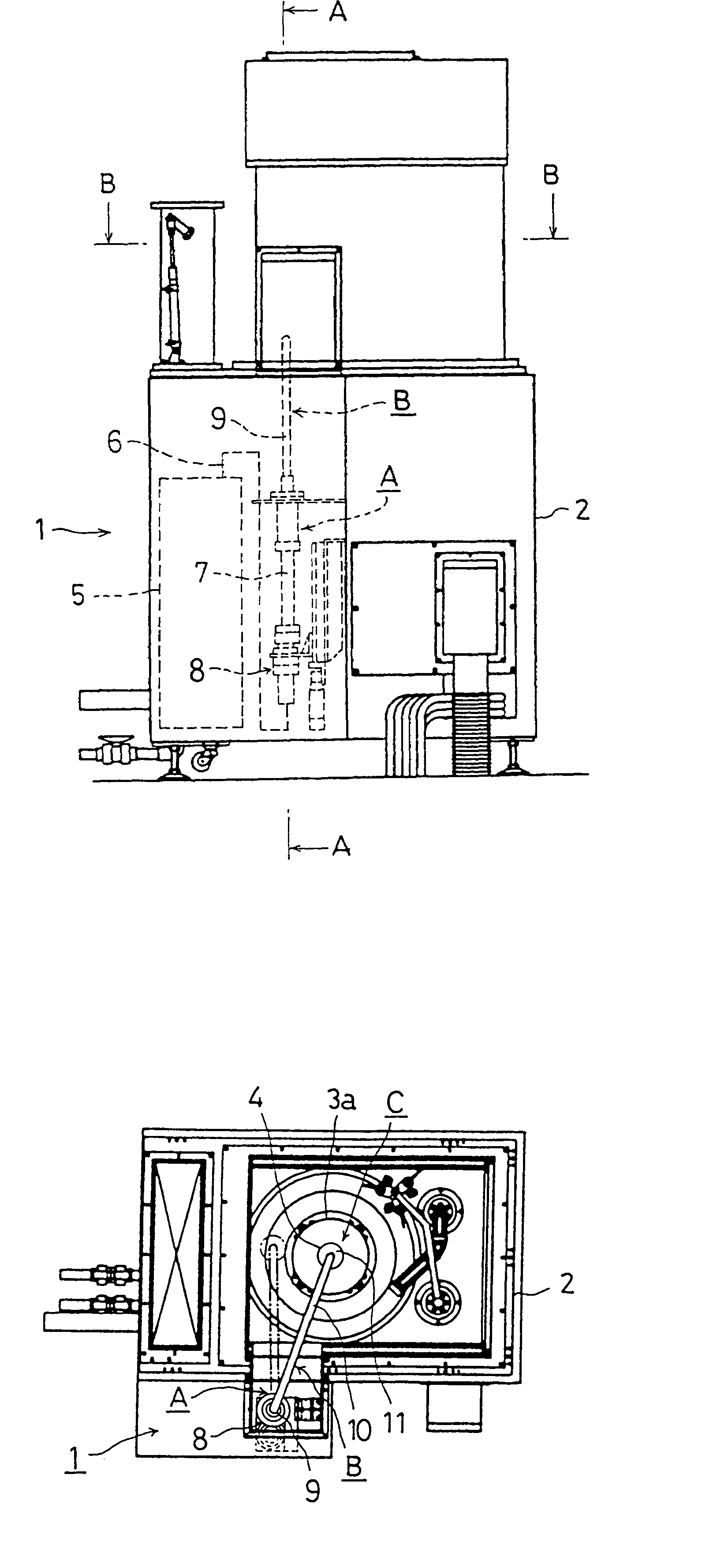
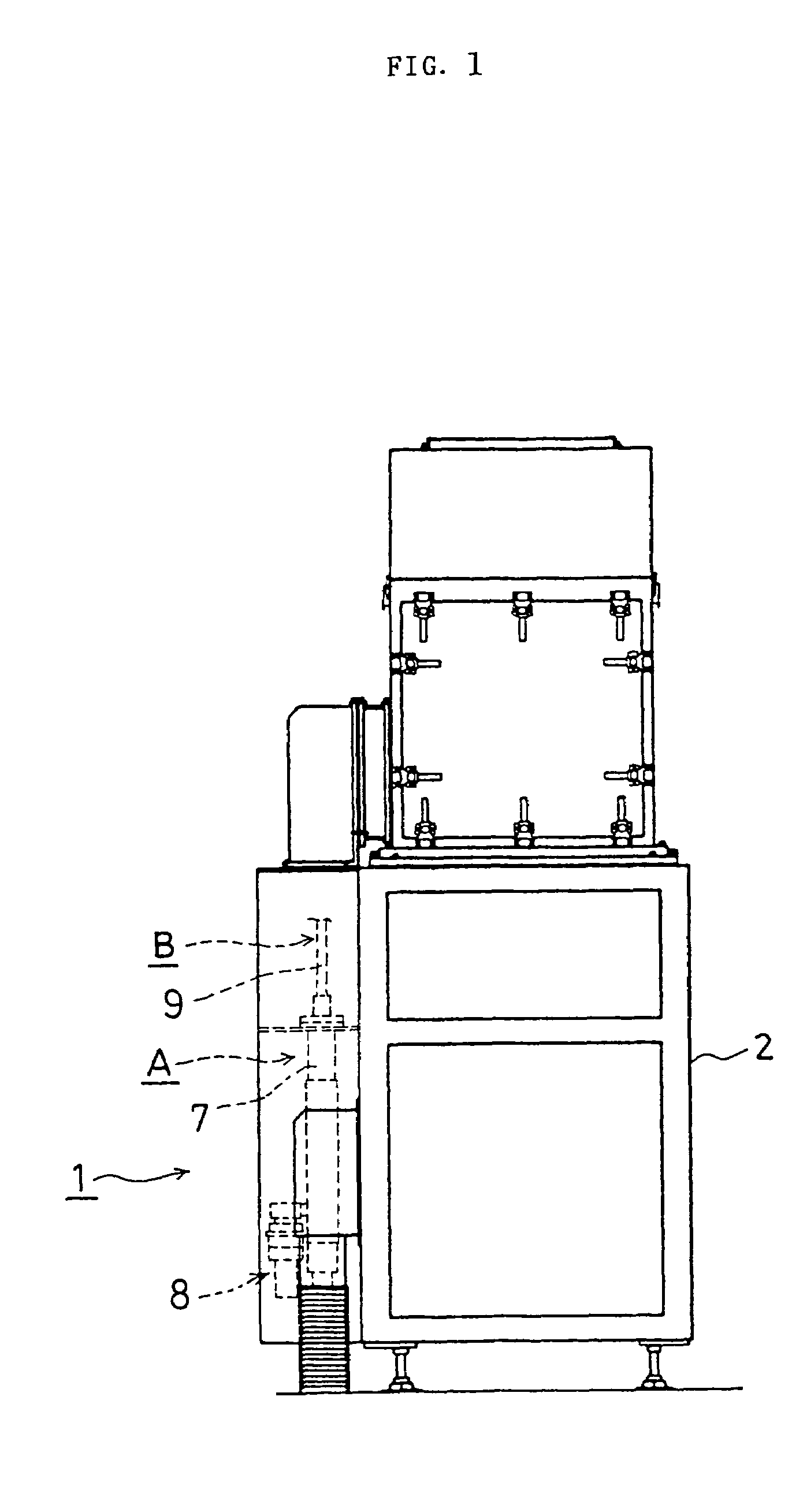
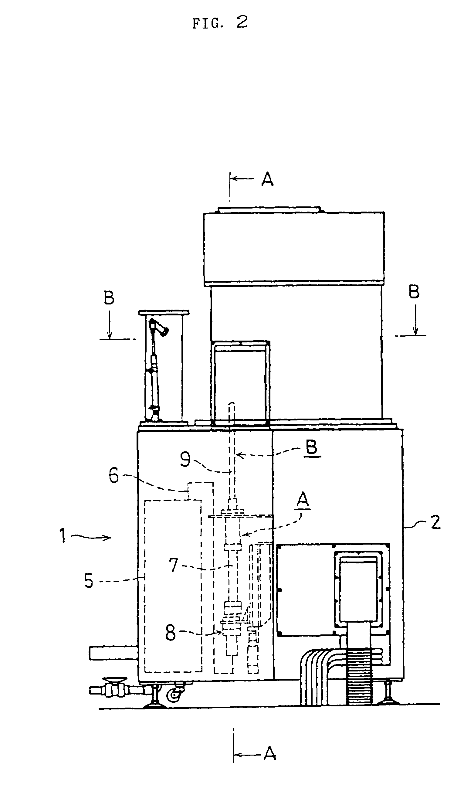
The present invention provides a rotation type silicon wafer cleaning device with a novel wafer drying device that can enhance the stability of the outer surface of the wafer after cleaning and drying. The device includes a wafer support / rotation driving device, a gas supply panel, a mixed gas heating device, and a hydrogen radical formation apparatus. The device can effectively prevent or delay the formation of a natural oxide film on the outer surface of the wafer and increase the bonding of silicon atoms with hydrogen atoms. The invention also provides a method for stabilizing the outer surface of the wafer after cleaning and drying. The technical effects of the invention include improved stability of the wafer surface, reduced formation of uncombined silicon atoms, and increased bonding of silicon atoms with fluorine atoms.

Problems solved by technology

However, even with a silicon wafer treated for cleaning with this kind of rotation type silicon wafer cleaning device, it is observed that an oxide film is naturally formed on the outer surface with the lapse of time after a cleaning is performed.
This makes it difficult to prevent the natural formation of the afore-mentioned oxide film no matter how well environmental conditions are presented for the maintenance of the wafer.

Method used


Image

  • Rotary silicon wafer cleaning apparatus
  • Rotary silicon wafer cleaning apparatus
  • Rotary silicon wafer cleaning apparatus

Examples


embodiment

[0136]A Si wafer 4 having an outer diameter of 60 mm φ is treated for cleaning with hydrofluoric acid and pure water, and rotates at the speed of 2000 RPM while its Si surface is completely exposed. And, then a mixed gas with H2 and N2 Containing H2 of 0.1% is supplied to a hydrogen radical formation / dispersion apparatus 11 at the speed of 30 SLM. The spacing between the filter 26 and the Si wafer is made 1 mm, thus making the mixed gas G gushed out for 2 minutes continuously through the space.

[0137]A filter 26 having the outer diameter of 54 mm φ, the thickness of 2.5 mm is formed in the shape of a disc comprising a sintered body made of a stainless-steel-made meshed net body having a pore with an average size of 20 μm and the temperature of the mixed gas at an inlet opening of the filter is set at 250° C.

[0138]When a wafer 4 dried and treated for the hydrogen termination with the silicon wafer drying device 1 in the afore-mentioned embodiment is left in the cleaned air for natural...


PUM


Abstract

It is an object of the present invention to provide a rotation type silicon wafer cleaning device to further raise the stability of a silicon wafer by providing a better hydrogen termination on the silicon wafer after completion of chemical and pure water cleaning treatments.According to the present invention, a rotation type silicon wafer cleaning device has a silicon wafer support / rotation driving mechanism inside the case body for cleaning the silicon wafer at the post chemical cleaning with pure water, drying and hydrogen termination treatments on the outer surface of a silicon wafer is performed by means of installing a silicon wafer drying device comprising a gas supply panel attached to a case body to supply a mixed gas of the hydrogen gas and inactive gas containing a hydrogen gas of more than 0.05%, a mixed gas supply pipe coupled to a gas mixer of the afore-mentioned gas supply panel at one end, a mixed gas heating device to heat the mixed gas in the afore-mentioned gas supply pipe, and a hydrogen radical formation apparatus equipped with a platinum coating film to form hydrogen radical at the gas contacting part where to a high temperature gas heated with the afore-mentioned mixed gas heating device touches, thus to gush out the mixed gas containing hydrogen radical formed with the afore-mentioned radical formation apparatus onto the rotating silicon wafer after cleaning is completed.

Description

[0001]This is a National Phase Application in the United States of International Patent Application No. PCT / JP03 / 11667 filed Sep. 11, 2003, which claims priority on Japanese Patent Application No. 2002-276818, filed Sep. 24, 2002. The entire disclosures of the above patent applications are hereby incorporated by reference.BACKGROUND OF THE INVENTION[0002]1. Field of the Invention[0003]The present invention relates to a rotation type silicon wafer cleaning device to be used with semiconductor fabrication equipment and the like, and more particularly to a rotation type silicon wafer cleaning device making possible substantial quality improvements in the products by stabilizing the outer surface of the silicon wafer through the improved hydrogen treatment of the outer surface of the silicon wafer through the drying process after cleaning is completed.[0004]2. Background of the Invention[0005]The fabrication of semiconductor elements generally starts with a cleaning treatment of a silic...

Claims


Application Information

Patent Timeline
Patent Type & Authority Patents(United States)
IPC IPC(8): F26B5/08F26B17/24H01L21/304F26B17/30H01LH01L21/00H01L21/02H01L21/30H01L21/302
CPCH01L21/67034H01L21/02052H01L21/304
Inventor OHMISHIRAI, YASUYUKIFUJITA, TAKUMIMINAMI, YUKIOIKEDA, NOBUKAZUMORIMOTO, AKIHIROKAWADA, KOJI
Owner FUJIKIN INC
Learn More