
Method of reducing NOx in diesel engine exhaust

a technology of diesel engine and nox, which is applied in the direction of machines/engines, separation processes, mechanical equipment, etc., can solve the problems of difficult reduction to nitrogen

Inactive Publication Date: 2006-08-15
GM GLOBAL TECH OPERATIONS LLC
View PDF13 Cites 41 Cited by
  • Summary
  • Abstract
  • Description
  • Claims
  • Application Information

AI Technical Summary

Benefits of technology

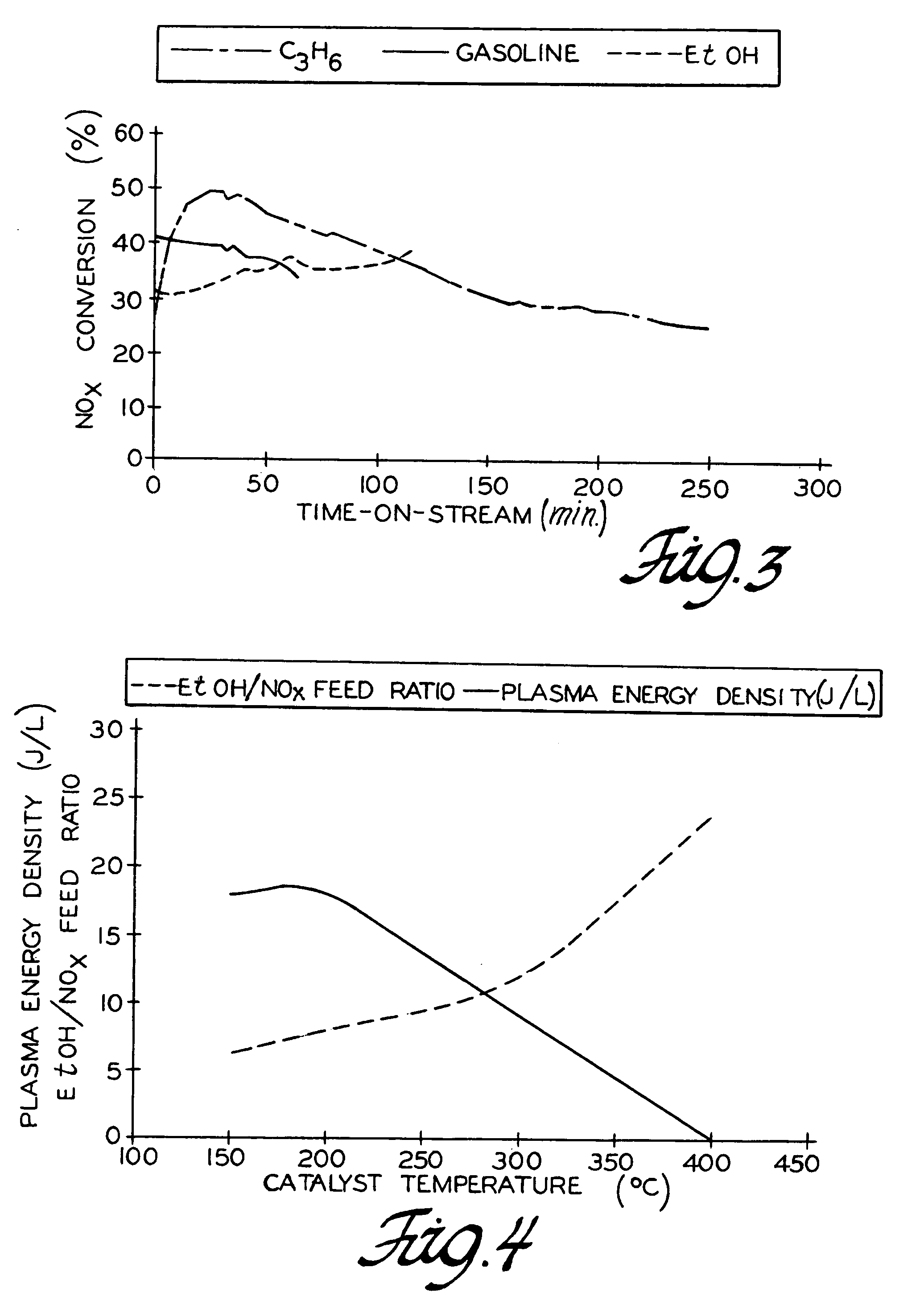
This patent describes a method for reducing NOx in exhaust gases from diesel engines using a dual bed catalyst with separate additions of ozone and ethanol. The method is effective in reducing NOx in hot gas streams with an abundance of oxygen. The use of plasma generated ozone and ethanol assists in the reduction of NO2 to N2 by oxidizing ethanol and participating in the reduction of NO2 to N2. The method is particularly useful for reducing NOx in exhaust streams from lean-burn power plants and engines. The plasma reactor used for generating ozone is a non-thermal plasma generator with a dielectric cylindrical wall and a helical ground electrode. The NOx content of the exhaust gas is monitored and the plasma power density and molar EtOH / NOx ratio are set and controlled based on the reduction catalyst temperature. The method achieves an average of 90% conversion of NOx to N2 over prolonged operation of the dual bed base metal-exchanged zeolite catalysts. The exhaust gas also contains unburned hydrocarbons and carbon monoxide which are preferably eliminated by catalytic oxidation and filtering of the exhaust prior to the ozone addition.

Problems solved by technology

These NOx gases, typically comprising nitric oxide (NO) and nitrogen dioxide (NO2), are difficult to reduce to nitrogen (N2) because of the high oxygen (O2) content in the hot exhaust stream.

Method used


Image

  • Method of reducing NOx in diesel engine exhaust
  • Method of reducing NOx in diesel engine exhaust
  • Method of reducing NOx in diesel engine exhaust

Examples


Embodiment Construction

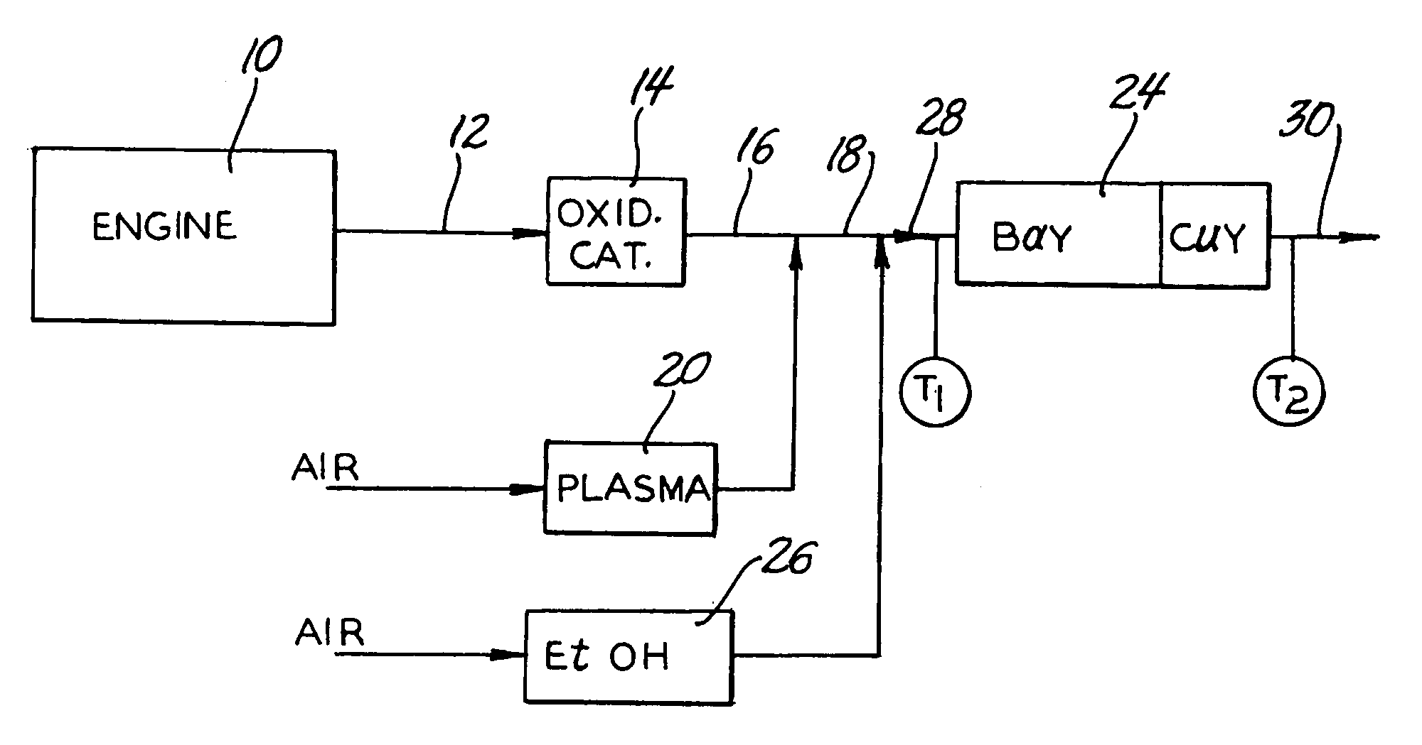
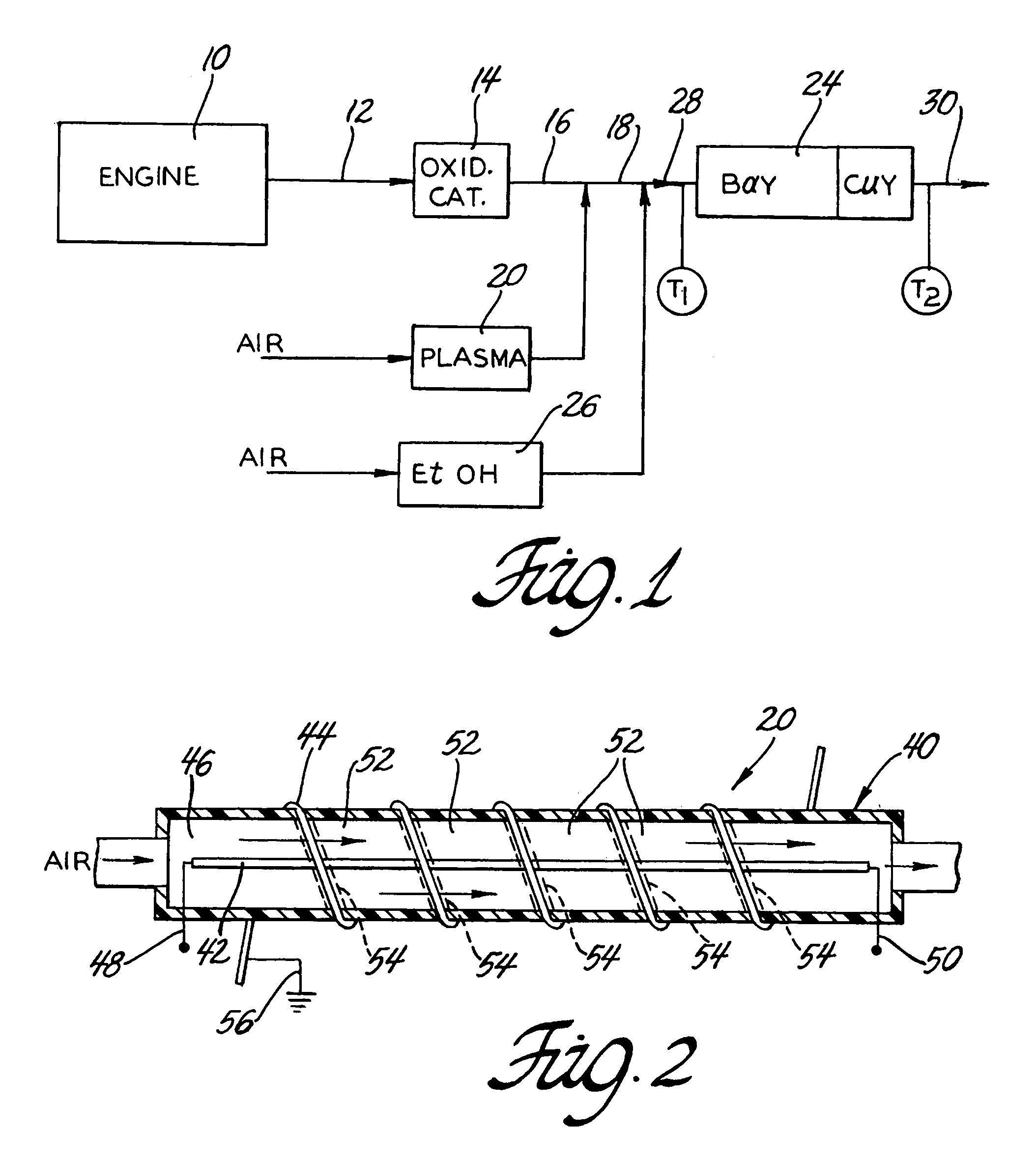
[0019]A practice of the invention is illustrated schematically in FIG. 1. Block 10 represents a diesel engine and line 12 represents the flow of the exhaust gas from the diesel engine 10. Diesel engines are typically operated at air to fuel mass ratios that are considerably higher than the stoichiometric ratio of air to fuel and the exhaust gas contains an appreciable amount of unreacted O2 as well as N2 (from the air). The temperature of the exhaust from a warmed-up engine is typically in the range of about 200° C. to about 400° C. The practice of the invention will be illustrated in the case of a diesel engine but it is to be understood that the subject method could be used to treat the exhaust of a lean burn gasoline engine or the exhaust of any hydrocarbon fueled power plant that uses an excess of air to burn the fuel. In diesel engine exhaust, in addition to O2 and N2, the hot gas also contains CO, CO2, H2O and hydrocarbons (some in particulate form) that are not completely bur...


PUM

PropertyMeasurementUnit
temperatureaaaaaaaaaa
temperaturesaaaaaaaaaa

Abstract

This invention provides a method of reducing nitrogen oxides in an oxygen containing exhaust stream using ethanol as a reductant for plasma-assisted selective catalytic reduction. The exhaust gas, generated from a diesel engine or other lean-burn power source, comprises nitrogen oxides, especially NO. Ozone generated from a plasma reactor is injected into the exhaust stream to convert NO to NO2 and the plasma injection is followed by the addition of ethanol. The NO2 is then reduced by contacting the exhaust stream with a dual-bed catalytic reactor comprising BaY (or NaY) and CuY zeolite catalysts in the presence of ethanol as the reductant. The plasma power density and the molar ratio of ethanol to NOx fed to the catalytic reactor are controlled as a function of the catalyst temperature for the best performance of the plasma-catalyst system. An average conversion of NOx to N2 of at least 90% is achieved over the temperature range of 200–400° C.

Description

TECHNICAL FIELD[0001]The present invention relates generally to treatment of exhaust gas from a hydrocarbon fueled power source, such as a diesel engine, operated with a fuel lean combustion mixture. More specifically, this invention pertains to treating the NOx content of the exhaust with the separate additions of ethanol and plasma treated air before passing the exhaust into contact with a base metal-exchanged zeolite catalyst.BACKGROUND OF THE INVENTION[0002]Diesel engines, some gasoline fueled engines and many hydrocarbon fueled power plants are operated at higher than stoichiometric air to fuel mass ratios for improved fuel economy. Such lean-burning engines and other power sources, however, produce a hot exhaust with a relatively high content of oxygen and nitrogen oxides (NOx). In the case of diesel engines, the temperature of the exhaust from a warmed up engine is typically in the range of 200° to 400° C. and has a typical composition, by volume, of about 17% oxygen, 3% carb...

Claims


Application Information

Patent Timeline
Patent Type & Authority Patents(United States)
IPC IPC(8): B01D53/56B01D53/86B01J8/00C01B21/00F01N3/20F01N13/00H05H1/24
CPCF01N3/2066F01N13/009H05H1/24F01N2240/28F01N2250/02F01N2610/03F01N2610/10Y02T10/24F01N2610/08H05H1/2406Y02T10/12H05H1/2465H05H1/245H05H2245/17F01N3/20B01D53/54F01N13/00
Inventor CHO, BYONG KWONLEE, JONG-HWAN
Owner GM GLOBAL TECH OPERATIONS LLC
Learn More