Eureka AIR delivers breakthrough ideas for toughest innovation challenges, trusted by R&D personnel around the world.

Runway approach lighting system and method

a runway approach and lighting system technology, applied in the direction of landing aids, lighting and heating equipment, instruments, etc., can solve the problems of premature failure of transformers, malsr's circuitry and components are susceptible to severe direction swings and magnitude surges in transformer excitation currents, and reduce operating expenses and runway downtime , simple design and economical manufacture and assembly, the effect of minimizing transformer excitation

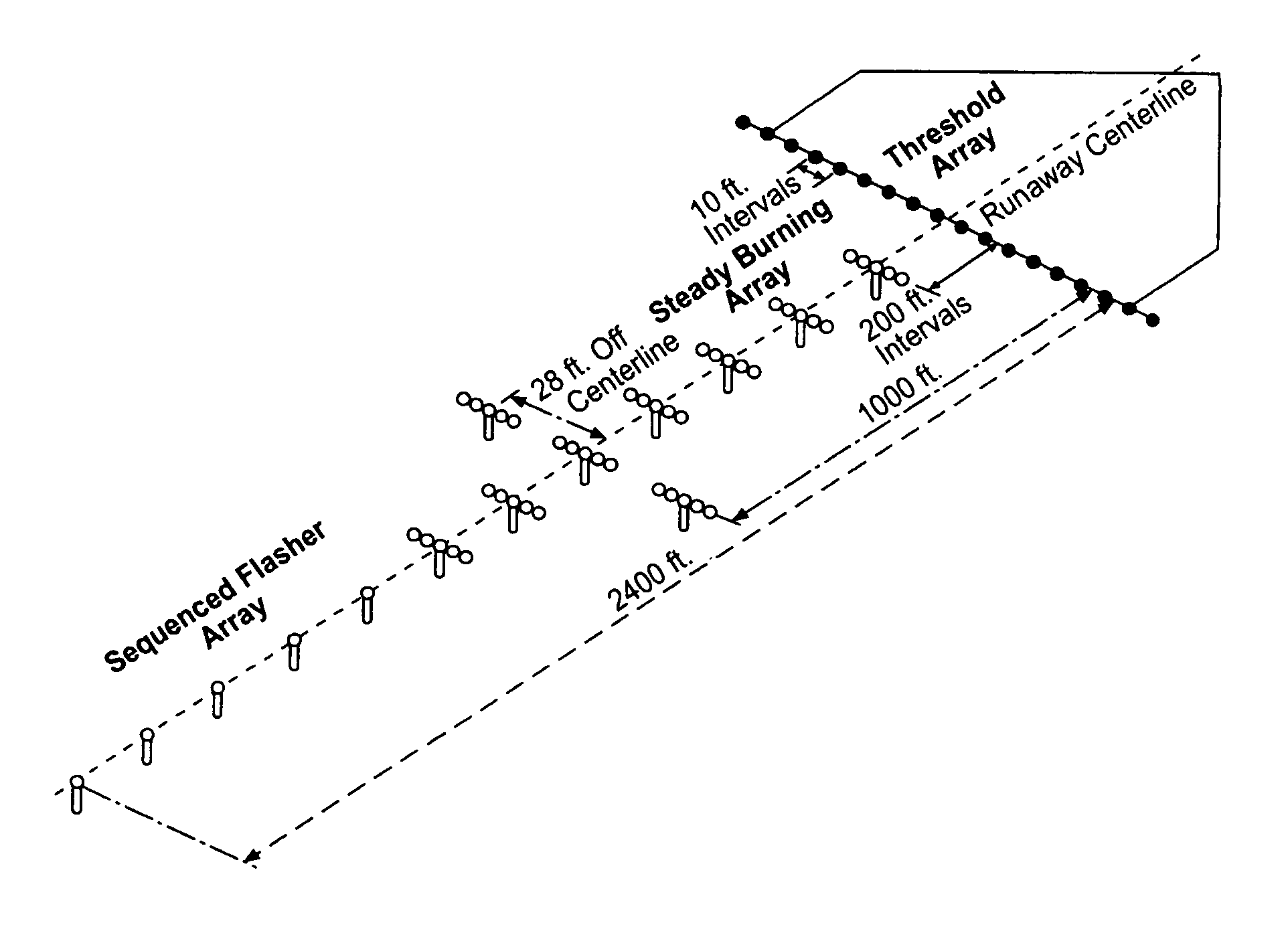
Inactive Publication Date: 2006-08-08
CONTROLLED POWER
View PDF20 Cites 16 Cited by
  • Summary
  • Abstract
  • Description
  • Claims
  • Application Information

AI Technical Summary

Benefits of technology

[0008]At least some of the objects, features and advantages that may be achieved by at least certain embodiments of the invention include providing a system that provides forced progressive increases in lighting intensity to prevent jumps from off or low intensity settings to medium or high intensity settings thereby minimizing transformer excitation; prevents simultaneous operation of switches without power dropout; extends the life of approach lighting lamps; allows for bypass operation; reduces operating expenses and runway downtime; is of relatively simple design and economical manufacture and assembly; and is reliable and has a long, useful service life.

Problems solved by technology

Unfortunately, however, current MALSR's are susceptible to relatively frequent electrical failure.
For example, the circuitry and components of MALSR's are susceptible to severe direction swings and magnitude surges in transformer excitation currents, typically caused by unintentional simultaneous operation of two of the three lighting intensity levels when switching between the different levels.
These swings and surges yield damaging electrical transients that lead to overstressing and premature failure of transformers, switch contactors, control circuit boards, the lamps and the like.
Moreover, the lightbars are particularly vulnerable to lightning strikes, which fault out the MALSR.
As a result of the above types of electrical failures, the MALSR must be diagnosed and repaired to return the MALSR to normal operation, which can take hours or days.
Diagnosis, repair, replacement of prematurely failed components, or simple reset of the MALSR creates guidance system down-time that, at best, is time consuming and expensive, and, at worst, increases the risk of landing an aircraft.

Method used


Image

  • Runway approach lighting system and method
  • Runway approach lighting system and method
  • Runway approach lighting system and method

Examples


Embodiment Construction

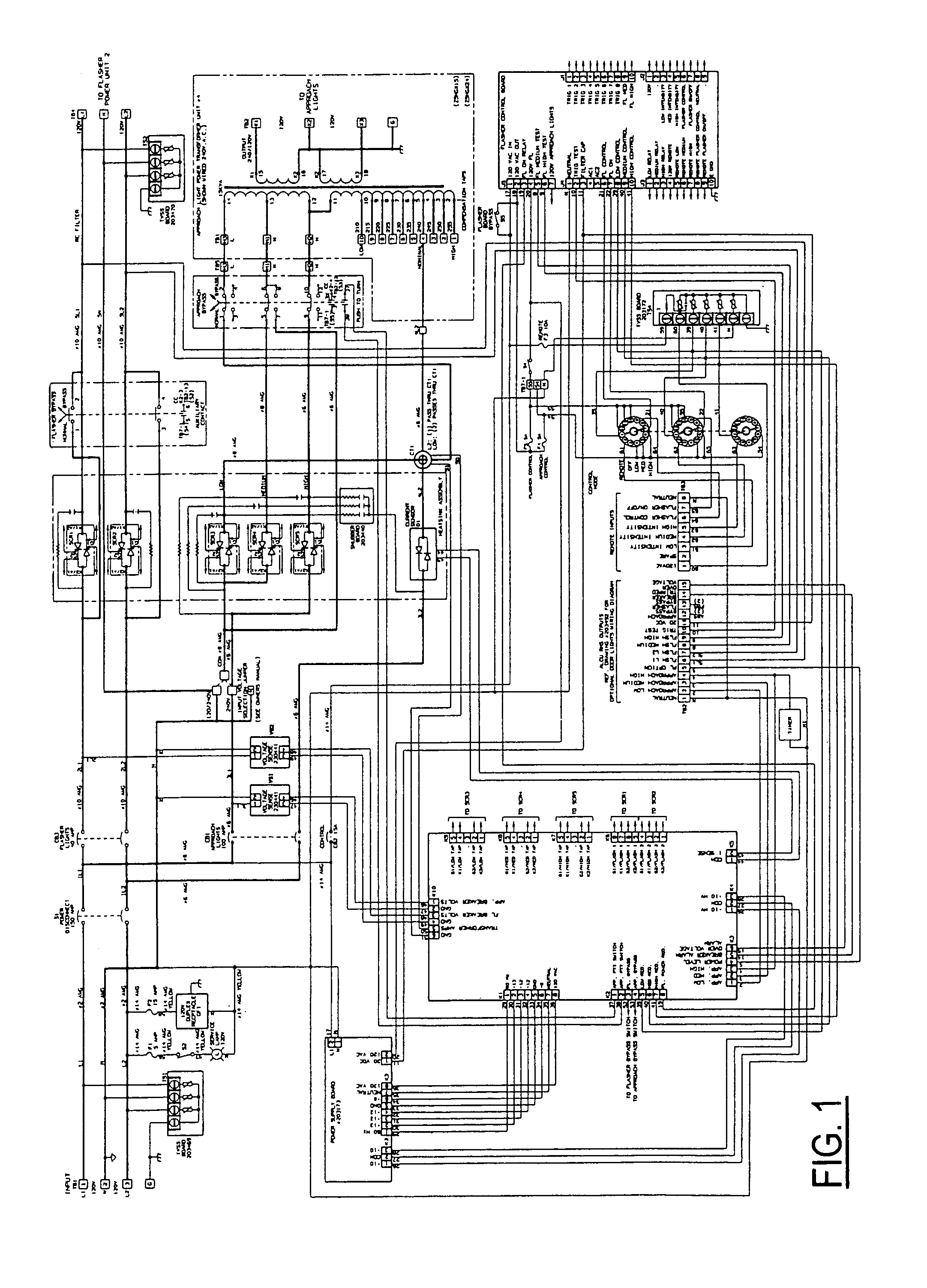
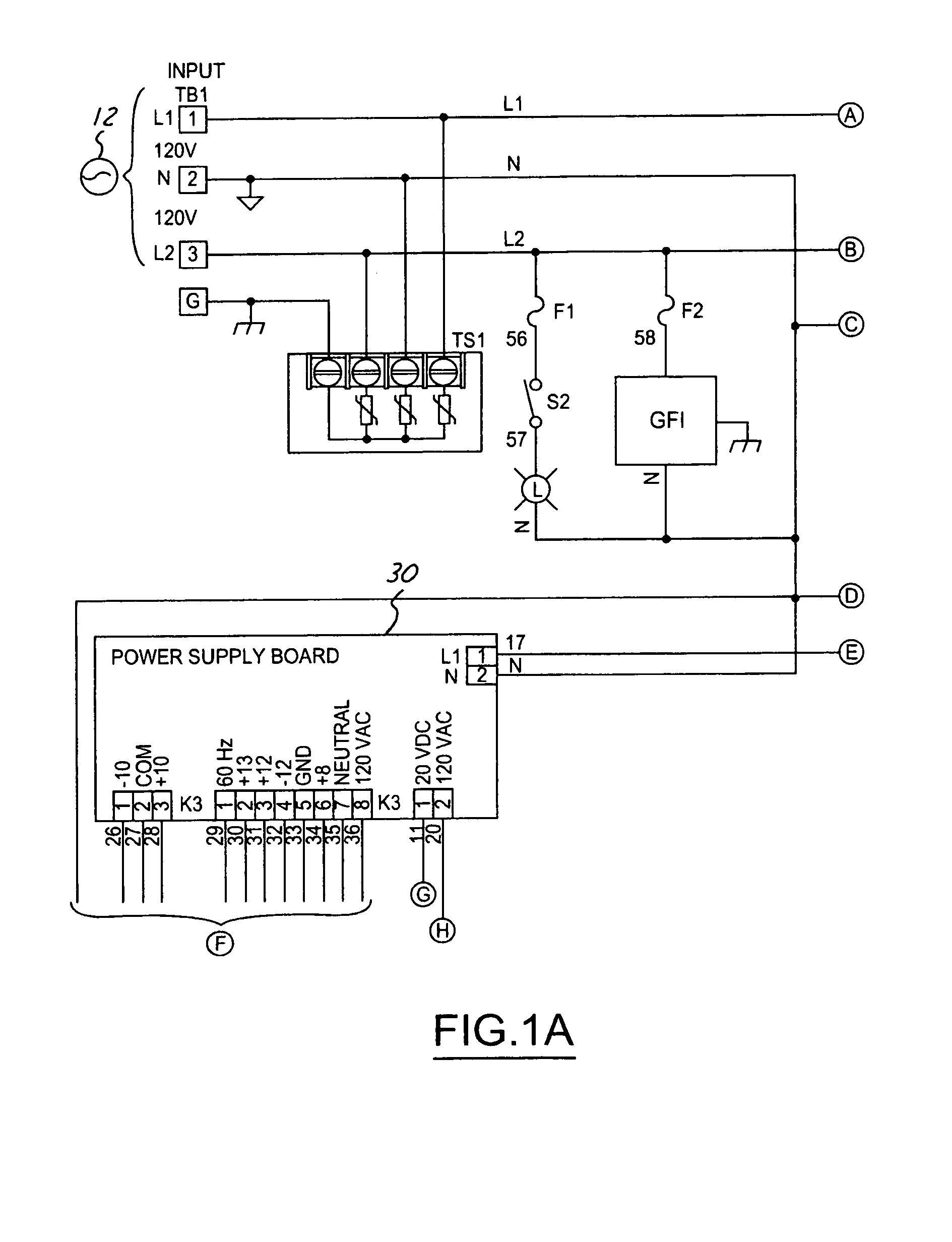
[0025]Referring in detail to the drawings, FIGS. 1–1H illustrate a schematic diagram of a portion of an aircraft landing guidance system 10 according to an embodiment of the present invention. The system 10 described herein generally provides controlling, bypassing, and power transforming for steady-burner approach lighting, and further includes interfacing to an approach light flasher system. As such, the system10 is provided primarily for powering and controlling the operation of steady-burning approach lights, as opposed to approach flashers or approach threshold lights. In any case, the present invention also contemplates systems and methods for controlling flashers and threshold lights in the same or a similar manner as described herein with respect to the approach lights. The system 10 of FIGS. 1–1H is comprised of control circuitry and power circuitry.

[0026]In the power circuitry portion of the system 10, a power source 12 provides a supply of 120 / 240 or 240 Volt, 60 Hertz po...


PUM


Abstract

A method and system for visually guiding an aircraft in its landing approach to a runway having an approach area equipped with approach lights operable in off, low, medium, and high intensity states. The lights are communicated with a secondary side of a transformer, which has a primary side with low, medium, and high taps that correspond to the light states. Off, low, medium, and high lighting intensity requests correspond to the low, medium, and high states of the plurality of lights. AC power is switched between the transformer taps in response to a request for an increase in lighting intensity. Power is sequentially applied to the taps by supplying the power to the low tap for a first predetermined time interval before supplying the power to the medium tap.

Description

CROSS-REFERENCES TO RELATED APPLICATIONS[0001]The present invention is a continuation-in-part of and is related to pending non-provisional application Ser. No. 10 / 863,421, filed Jun. 8, 2004, and entitled “RUNWAY APPROACH LIGHTING SYSTEM AND METHOD”, by Krause et al, and to provisional application Ser. No. 60 / 603,972, filed on Aug. 24, 2004, and also entitled “RUNWAY APPROACH LIGHTING SYSTEM AND METHOD”. Each of the above listed cross-references is assigned to the assignee of the present invention, is incorporated by reference herein, and domestic priority is claimed thereto.FIELD OF THE INVENTION[0002]This invention relates generally to aircraft indicating systems and methods, and more particularly to visual aircraft landing guidance systems and methods.BACKGROUND OF THE INVENTION[0003]Visual landing guidance systems for aircraft are widely used throughout the world as an aid for guiding an aircraft in descent to a runway. Such systems include the medium intensity approach lighting...

Claims


Application Information

Patent Timeline
Patent Type & Authority Patents(United States)
IPC IPC(8): G08G5/00H05B45/50
CPCG08G5/0026G08G5/025H05B33/0884H05B33/0842H05B33/0806H05B45/50H05B45/382
Inventor KRAUSE, KENNETH NICHOLASBUSBY, VINCENT ROBERT
Owner CONTROLLED POWER
Why Eureka
Eureka Blog
Learn More