Plasma production device and method and RF driver circuit with adjustable duty cycle

a technology of rf driver and production device, applied in the direction of individual energised antenna array, plasma technique, energy-based chemical/physical/physico-chemical processes, etc., can solve the problems of affecting the antenna loading, the degree of automation is limited, and the accuracy of tuning these components is often difficult. achieve the effect of efficient coupling of rf sources

Inactive Publication Date: 2006-08-01
PLASMA CONTROL SYST LLC +1
View PDF44 Cites 46 Cited by
  • Summary
  • Abstract
  • Description
  • Claims
  • Application Information

AI Technical Summary

Benefits of technology

The present invention provides an improved antenna design for efficiently coupling RF sources to a plasma without the need for a matching network. The system includes a plasma source, a radio frequency power source, a static magnetic field, and a reactance coupling the switching amplifier to the antenna loops. The RF power source can have a low output impedance, and the system can operate efficiently and robustly in pressure regimes that are difficult to access and use with other plasma sources. The combination of antenna system and RF generator can create and maintain a plasma under conditions where the plasma parameters vary over much larger ranges than other sources without the need for adjusting any matching network components. The system can also control the spatial distribution of the working gas within the reaction chamber to improve the uniformity of the plasma initiation time. The plasma source can operate as a helicon mode RF wave or a type of inductively coupled plasma device.

Problems solved by technology

In addition, the amplitude of the RF drive waveform itself affects the plasma temperature and density, which in turn also affects the antenna loading.
Not surprisingly, accurate tuning of these components is often a difficult process.
Typically, retuning requires manual / mechanical operations / actuators to adjust one or more component values and generally sophisticated feedback circuitry for the rather limited degree of automation possible.
This leads to an increase in the induced currents, resulting in the electrical breakdown and substantial ionization of the gas by various mechanisms.
However, these designs are relatively complex often requiring custom components that increase the cost of system acquisition and maintenance.
Moreover, not all of the designs are suitable for efficient generation of the helicon mode, which is a preferred mode disclosed herein.
In power amplification, an important concern is the amount of power wasted as heat, since heat sinks must be provided to dissipate the heat and, in turn, increase the size of devices using an inefficient amplifier.
These matching networks add to the complexity for operation with a switched mode power supply rather than eliminate the dynamic matching network.
The problems faced in efficient plasma generator design include the need for a low maintenance and easily configured antenna, the elimination of expensive and limited matching networks to couple the RF power source to the non-linear dynamic impedance presented by a plasma, and the need for RF power sources that can be efficiently modulated.

Method used


Image

  • Plasma production device and method and RF driver circuit with adjustable duty cycle
  • Plasma production device and method and RF driver circuit with adjustable duty cycle
  • Plasma production device and method and RF driver circuit with adjustable duty cycle

Examples


Embodiment Construction

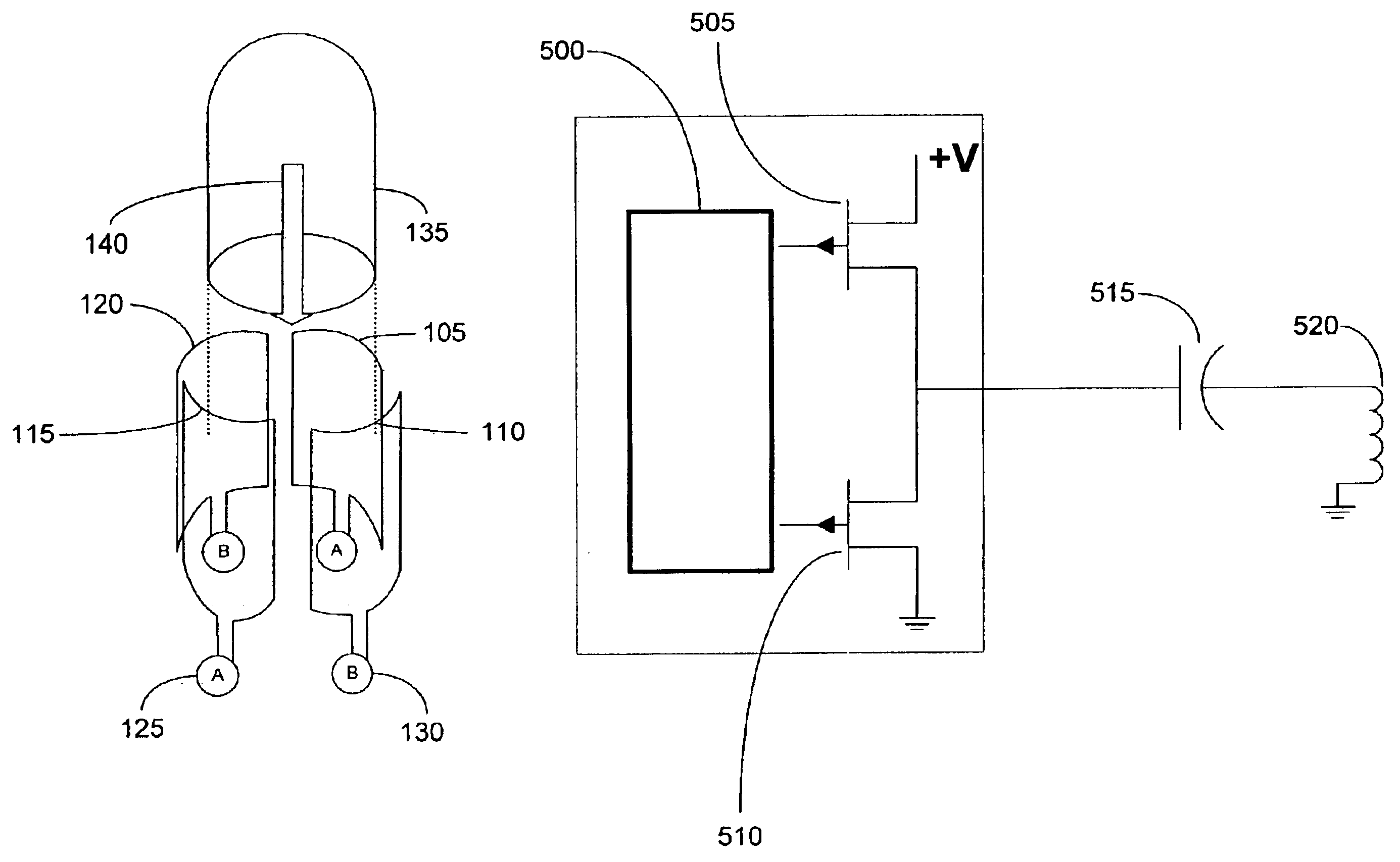
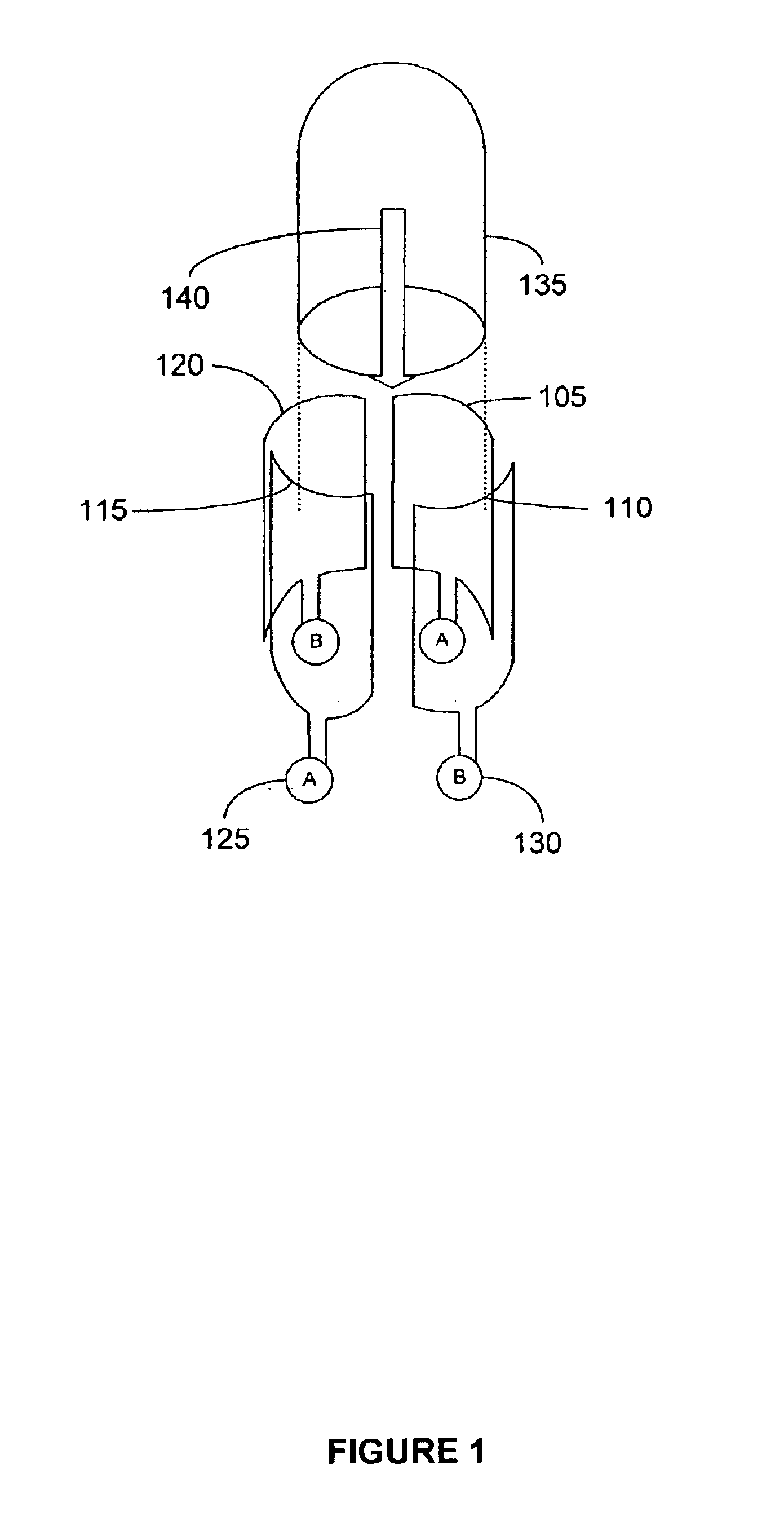
[0038]Turning first to the figures, FIG. 1 illustrates a plasma source chamber with two sets of antenna elements configured in accordance with an embodiment of the present invention. The antenna design includes two orthogonal single- or multi-turn loop elements 105, 110, 115, and 120, arranged about a common axis. The antenna elements 105, 110, 115, and 120 are each driven by RF power sources, A 125 or B 130 as shown. Each antenna loop may be coupled to the same RF power source with a phase splitter, or to distinct RF power sources, to drive the antenna elements in quadrature. Preferably the loops in the antenna are constructed from eight (8) gauge teflon coated wire although copper wire or other conductors may also be used.

[0039]FIG. 1 shows two orthogonal sets of two-element Helmholtz-coil-like loop antennas, with loop elements 105 and 115 in one set and loop elements 110 and 120 in the second set. The loop elements are wrapped azimuthally around an insulating cylinder 135 such th...


PUM


Abstract

An RF driver circuit and an orthogonal antenna assembly / configuration, are disclosed as part of a method and system for generating high density plasma. The antenna assembly is an orthogonal antenna system that may be driven by any RF generator / circuitry with suitable impedance matching to present a low impedance. The disclosed RF driver circuit uses switching type amplifier elements and presents a low output impedance. The disclosed low-output impedance RF driver circuits eliminate the need for a matching circuit for interfacing with the inherent impedance variations associated with plasmas. Also disclosed is the choice for capacitance or an inductance value to provide tuning for the RF plasma source. There is also provided a method for rapidly switching the plasma between two or more power levels at a frequencies of about tens of Hz to as high as hundreds of KHz.

Description

REFERENCE TO RELATED APPLICATIONS[0001]This application claims the benefit under U.S.C. §119 and is a continuation-in-part of Ser. No. 10 / 268,053 filed Oct. 8, 2000 and claims benefit of the U.S. Provisional Application No. 60 / 328,249 filed on Oct. 9, 2001, which is incorporated herein in its entirety by reference.FIELD OF THE INVENTION[0002]The present invention relates generally to the design and implementation of a plasma generation system. More particularly, it relates to radio frequency amplifiers, antennas and effective circuit connections for interfacing the amplifiers and antennas for generating plasma.BACKGROUND OF THE INVENTION[0003]Plasma is generally considered to be a fourth state of matter, the others being solid, liquid and gas states. In the plasma state the elementary constituents of a substance are substantially in an ionized form rendering them useful for many applications due to, inter alia, their enhanced reactivity, energy, and suitability for the formation of ...

Claims


Application Information

Patent Timeline
Patent Type & Authority Patents(United States)
IPC IPC(8): H01Q7/00H03H7/38H05B37/02H01J37/32H01Q21/20H05H1/46
CPCH01J37/32082H01J37/321H01J37/32128H05H1/46H01J37/32522H01Q7/00H01Q21/205H01J37/32174H05H1/36
Inventor PRIBYL, PATRICK A.
Owner PLASMA CONTROL SYST LLC
Why Eureka
Try Eureka