Backlight apparatus for illuminating a display with controlled light output characteristics

Inactive Publication Date: 2000-06-06
UNITED CALIFORNIA BANK +1
View PDF62 Cites 137 Cited by
  • Summary
  • Abstract
  • Description
  • Claims
  • Application Information

AI Technical Summary

Benefits of technology

A primary object of the invention is to provide an apparatus that efficiently couples light from the illumination source into the waveguide. Another object of the invention is to provide an apparatus that collimates the light from the illumination source so that the maximum amount of light from the illumination source can be coupled through the polarizer of the liquid crystal display. Another object of the invention is to provide an apparatus that increases the brightness of a liquid crystal display. Another object of the invention is to provide an apparatus having lower power consumption. Another object of the invention is to provide an apparatus with more homogenous light distribution. Another object of the invention is to provide an apparatus that is cost effective. Another object of the invention is to provide an apparatus having directionality. Another object of the invention is to provide an apparatus that is rugged and reliable, thereby decreasing down time and operating costs. Another object of the invention is to provide an apparatus that has one or more of the characteristics discussed above but which is relatively simple to manufacture and assemble using a minimum of equipment.
Another object of the invention is to provide a method that can be used to illuminate a liquid crystal display. Another object of the invention is to provide a method that is predictable and reproducible, thereby decreasing variance and operating costs. Another object of the invention is to provide a method that has one or more of the characteristics discussed above but which is which is relatively simple to setup and operate using relatively low skilled workers.

Problems solved by technology

In the past, this coupling has been inefficient.
Thus, a previously recognized problem has been that much of the light available from the illumination source is wasted resulting in decreased brightness.
However, efficient coupling between the illumination source and the waveguide is not sufficient.
Another previously recognized problem has been that liquid crystal displays are not bright enough for use in high ambient light conditions.
Another previously recognized problem has been that the light transmitted through liquid crystal display systems is not homogeneous.
One unsatisfactory previously recognized approach, which attempts to solve the efficiency and homogeneity problems referred to herein, involves replacing the metallized bottom surface with a surface that includes a number of white dots.
However, this previously recognized approach has the disadvantage of relatively low coupling efficiency.
Further, this previously recognized approach also has the disadvantage that the white dots do not collimate the light.
Moreover, this previously recognized approach also has the disadvantage of relatively high cost.
Yet another previously recognized problem has been that much of the light transmitted through liquid crystal display systems is wasted because it is not seen.
Heretofore, the above-discussed requirements have not been fully met.

Method used


Image

  • Backlight apparatus for illuminating a display with controlled light output characteristics
  • Backlight apparatus for illuminating a display with controlled light output characteristics
  • Backlight apparatus for illuminating a display with controlled light output characteristics

Examples


Embodiment Construction

The present invention and the various features and advantageous details thereof are explained more fully with reference to the nonlimiting embodiments described in detail in the following description. Before describing the present invention in detail, a graphical review of prior art structures in FIGS. 1-2 is in order.

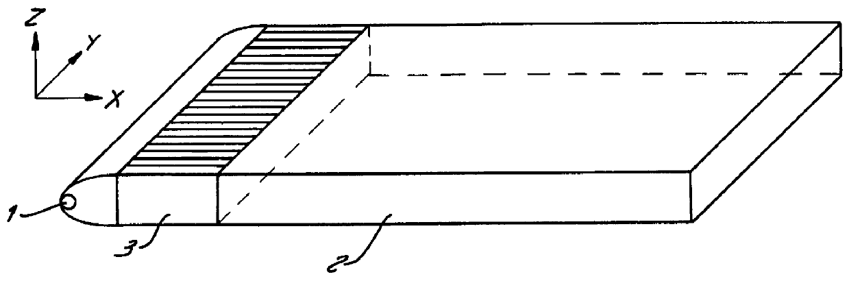
Referring to FIG. 1, a conventional liquid crystal display backlight is shown where light from illumination source 1 travels to backlighting light pipe 2 through separate light pipe 3. Separate light pipe 3 is divided into a number of laterally adjacent sections.

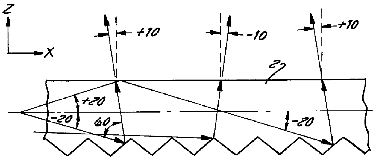
Referring now to FIG. 2, a partial cross sectional view of the backlighting light pipe 2 in FIG. 1 is shown. The divergence of the incoming light is reduced.

1. System Overview

The above-mentioned requirements of high brightness, low power consumption, homogeneity and directionality are to some extent mutually contradicting and cannot be satisfied simultaneously in the case of a conventional liquid crystal displa...


PUM


Abstract

Systems and methods for providing an LCD backlight are described. An LCD backlight system includes: a beam bending and viewing film including a first side including a surface diffuser and a second side including a plurality of substantially parallel optical elements, each of the plurality of substantially parallel optical elements including a first facet that includes a refractive surface and a second facet that includes a total internal reflection surface. The systems and methods provide advantages in that light from the LCD backlight is bright and homogenous.

Description

1. Field of the InventionThe present invention relates in general to the field of liquid crystal display (LCD) systems. More particularly, the present invention relates to a liquid crystal display that is illuminated with collimated backlighting. In a preferred embodiment, the present invention relates to a liquid crystal display system that includes a collimating backlight and a non-Lambertian diffuser. The present invention thus relates to liquid crystal display systems of the type that can be termed collimated backlit non-Lambertian diffused.2. Discussion of the Related ArtWithin this application, several publications are referenced by arabic numerals within parentheses. Full citations for these, and other, publications may be found at the end of the specification immediately preceding the claims. The disclosures of all these publications in their entireties are hereby expressly incorporated by reference into the present application for the purposes of indicating the background o...

Claims


Application Information

Patent Timeline
IPC IPC(8): F21V8/00G02F1/13G02F1/1335G02B6/00G02F1/13357
CPCG02B6/0038G02B6/0053G02B6/0018G02B6/0031G02B6/0036G02F2001/133607G02B6/0061G02B6/0068G02F1/133615G02F1/133607
Inventor JANNSON, TOMASZ P.JANNSON, JOANNA L.KUPIEC, STEPHEN A.LATCHINIAN, JACK L.
Owner UNITED CALIFORNIA BANK
Why Eureka
Try Eureka