
Method for fabricating vacuum container and method for fabricating image-forming apparatus using the vacuum container

a vacuum container and image-forming technology, which is applied in the manufacture of electrode systems, discharge tubes with screens, discharge tubes luminescnet screens, etc., can solve the problems of difficult to obtain the functions of the above 1> and 2>, spacer breakage, and jointing temperature rise, so as to avoid unnecessary activation of the getter material and improve the effect of conductan

Inactive Publication Date: 2006-07-25
CANON KK
View PDF24 Cites 9 Cited by
  • Summary
  • Abstract
  • Description
  • Claims
  • Application Information

AI Technical Summary

Benefits of technology

[0017]It is preferable that the first substrate is jointed with the frame member by disposing a spacing definition member higher than the frame member and lower than a frame member disposed through a first jointing material on the main surface of the first substrate and pressing gaps between the first substrate on which the frame members and the spacing definition member are disposed, the frame members, and the spacing definition member and thereby keeping the height of the frame member disposed through the first substrate and that of the spacing definition member almost the same. In this case, it is possible to control the sinking distance of the frame into the first jointing material. Therefore, even if using a jointing material having a low melting point for which a buffering function cannot be expected to joint the second substrate with the frame member to be performed later, it is possible to form a vacuum container having a high airtightness because the height of the frame member (height of junction face with second substrate) is uniform.
[0021]In this case, because pressurization can be controlled, it is possible to uniformly pressurize a frame and resultantly, it is prevented that the entire upper face of the frame is diagonally jointed when assembling the frame. Therefore, this is more preferable.
[0023]Moreover, it is preferable that the first jointing material is made of frit glass. In this case, frit glass function as buffering materials and thereby, it is possible to absorb the warpage or strain of the frame member or substrate. In this connection, for the purpose of reducing damages to the electron emitting elements, it is preferable to apply the frit glass to the frame member. In this case, it is possible to reduce the number of heat-processing experiences to the electron emitting elements such as provisional baking etc.
[0025]When providing the getter material to the substrate, it is preferable to perform a low-temperature treatment in order to avoid unnecessary activation of the getter material when assembled. Therefore, it is preferable to selectively provide a getter member to the second substrate to be jointed with the frame member by a low-melting-point jointing material (such as low-melting-point metal). Thereby, it is possible to keep the inside of the vacuum container in a vacuum state. Moreover, because a spacer is set in the vacuum container, a conductance may be deteriorated. However, deterioration of the conductance is solved by providing a getter to the second substrate and it is possible to sufficiently show the function of the getter. In a case of using a low-melting-point metal as the second jointing material such as a case were the second substrate has a getter, it is preferable to joint the first substrate with the frame member by using the above spacing definition member. Because it is impossible to expect the buffering function of frit glass for a low-melting-point metal, it is preferable to uniformly set frame heights by using the spacing definition member when jointing the first substrate (e.g. rear plate) with the frame.

Problems solved by technology

400° C.) treatment such as a bonding step using frit is applied to the above spacer, a problem may occur that the spacer is broken due to its shape or characteristics of the antistatic treatment applied to the surface of the spacer may be changed.
However, when using only a low-temperature jointing material, it is difficult to obtain the functions of the above and .
Moreover, when frit glass is mixed, a jointing temperature rises and the problems of the above and occur.

Method used


Image

  • Method for fabricating vacuum container and method for fabricating image-forming apparatus using the vacuum container
  • Method for fabricating vacuum container and method for fabricating image-forming apparatus using the vacuum container
  • Method for fabricating vacuum container and method for fabricating image-forming apparatus using the vacuum container

Examples


embodiment 1

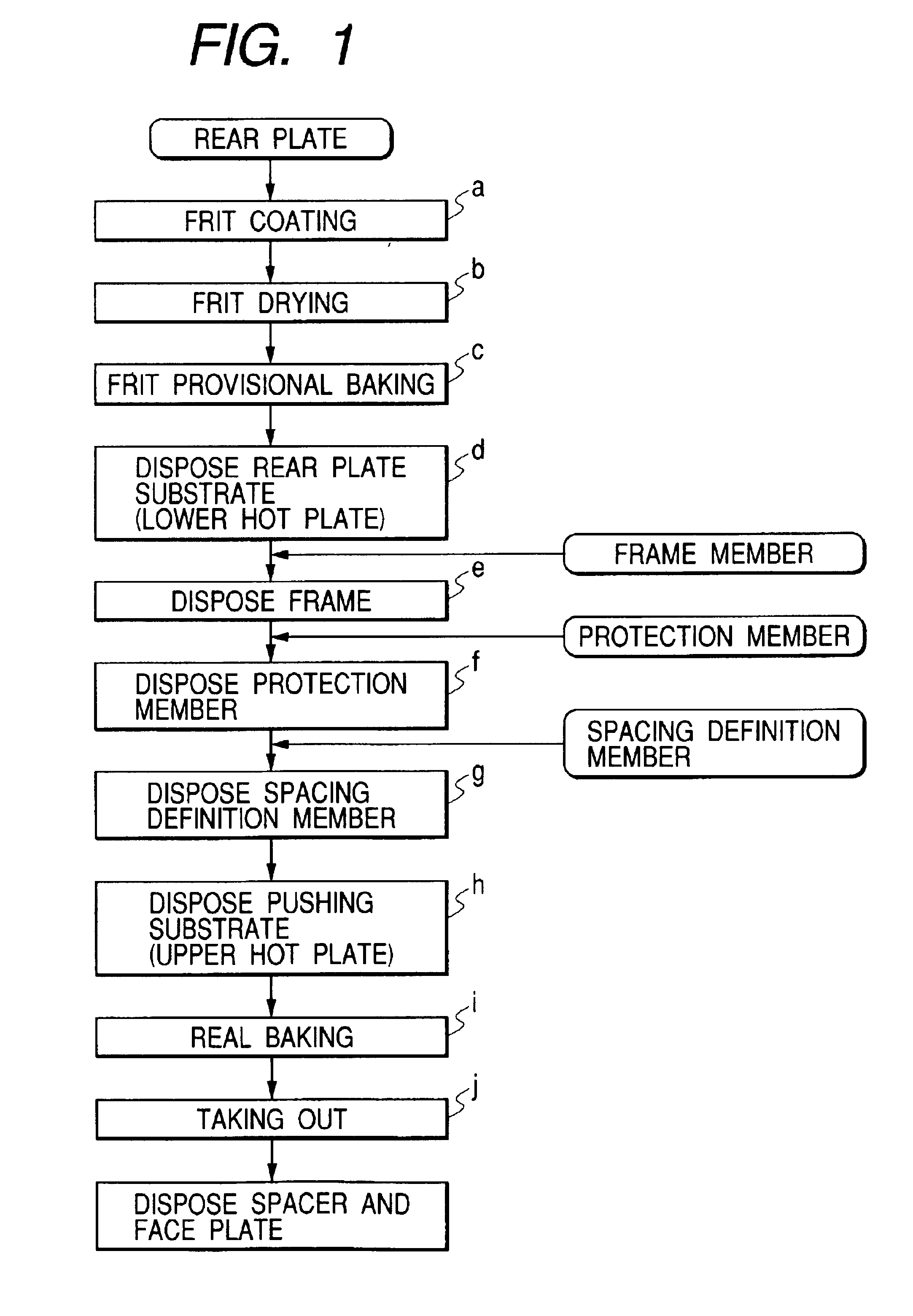
[0047]Then, an embodiment of the present invention is described below by referring to the accompanying drawings. However, a schematic configuration of a display unit which is an embodiment of an image-forming apparatus of the present invention is the same as that disclosed in the official gazette of Japanese Patent Application Laid-Open No. 09-82245, its description will be described later but jointing between a substrate, particularly, a rear plate (first substrate) and a frame and jointing between the rear plate and a spacer are mainly described below in detail.

[0048]Therefore, though a bonding step of a frame member when fabricating a display unit is described below by referring to FIGS. 1 to 11, the outline of an assembling system used for a frame jointing step is described below by referring to FIG. 2.

[0049]FIG. 2 is a block diagram of a hot-plate-type assembling system used to assemble a frame member of a display unit which is an embodiment of the present invention, in which s...

embodiment 2

[0103]Then, embodiment 2 of the present invention is described below. In the case of this embodiment, steps from the step h downward in the above first embodiment are different. Therefore, only different steps are described below. The embodiment 2 uses a clip as pressuring means and a baking furnace as baking means. Then, steps from the step h downward of this embodiment are described below.

h. (Clip Fixing Step)

[0104]The spacing definition member 71, frame 51, and rear plate 31 assembled as described above are fixed by clips 92. The clip 92 are uniformly disposed at four sides so that a uniform pressure can be applied to the whole frame 51 (refer to FIG. 16).

[0105]The clip 92 is used to fix the position of the frame 51 and pressurize frit glass (first jointing material) 33 in a heating step to be described later and therefore, it has heat resistance and a desired spring force. Therefore, a material is not restricted as long as the material satisfies the above conditions. A clip made...


PUM


Abstract

A method that makes uniform the frame height after joining a frame and a substrate constituting the vacuum container of an image-forming apparatus without damaging the substrate surface in the vacuum container. A frame member is joined with a rear plate by applying frit glass to the rear plate, disposing a frame member on the frit glass, disposing a spacing definition member to a portion of the rear plate nearby the frame member where the vacuum container is not formed, pressurizing the frame member, and then softening the frit glass and thereby joining the frame member with the rear plate.

Description

BACKGROUND OF THE INVENTION[0001]1. Field of the Invention[0002]The present invention relates to a method for fabricating a vacuum container and a method for fabricating an image-forming apparatus using the vacuum container.[0003]2. Related Background Art[0004]In recent years, applied researches using an electron source constituted by arranging many electron discharge elements on a flat substrate have been extensively performed and for example, development of image-forming apparatuses such as an image display unit and an image recorder has been progressed. Particularly, a thin flat image display unit is watched as a substitute for a cathode-ray-tube display unit because it is space-saving and lightweight. As this type of the flat display unit, a display unit is proposed in which an electron-source substrate (rear plate) obtained by arranging electron discharge elements like a matrix and a face plate having a phosphor disposed so as to face the substrate are formed into an airtight c...

Claims


Application Information

Patent Timeline
Patent Type & Authority Patents(United States)
IPC IPC(8): H01J9/00H01J9/26H01J9/40H01J17/20H01J5/24H01J9/24H01J31/12
CPCH01J5/24H01J9/241H01J9/261H01J31/123H01J9/242H01J2329/8625H01J9/26H01J11/34
Inventor TAGAWA, MASAHIROTAKAMATSU, OSAMUKOYAMA, SHINYA
Owner CANON KK
Learn More