Fast bit-error-rate (BER) test

a bit-error rate and test technology, applied in the field of digital testing, can solve the problems of reducing customer satisfaction, general slowness, and testing can add a significant amount of time and expense to the manufacture of digital devices

Active Publication Date: 2006-07-18
TEXAS INSTR INC
View PDF4 Cites 9 Cited by
  • Summary
  • Abstract
  • Description
  • Claims
  • Application Information

AI Technical Summary

Benefits of technology

[0011]The present invention provides a number of advantages. For example, use of a preferred embodiment of the present invention permits a fast, hardware-based test of the bit-error-rate of a device due to its ability to provide compensation for the variable delay introduced by the test system and the device.
[0012]Also, use of a preferred embodiment of the present invention the use of existing BER testing hardware to be used with minor modifications, permitting an easy migration to a test system using the present invention.
[0013]Additionally, a preferred embodiment of the present invention has applicability to the testing of any device requiring a BER test on any test hardware fixture.

Problems solved by technology

Testing helps in ensure the functionality of devices while it reduces the probability of shipping faulty products, which would result in a return and reduction in customer satisfaction.
While digital testing is a necessary step of the manufacturing process, it is in general slow.
Therefore, testing can add a significant amount of time and expense to the manufacture of a digital device.
A wireless device with a high BER will sound poorly (if it is a communications device) or perform poorly with a low data rate (if it is a data device).
A difficulty associated with performing the BER test is aligning the known data stream with the data stream from the device prior to a decoding stage.
This is due to delays introduced into the test system by the testing hardware and the device itself.
Therefore, there is not a constant amount of delay that can be readily compensated.
Unfortunately, a software implementation of the BER test is extremely slow.
Its inherent lack of speed tends to either shorten the BER test being performed or to reduce the number of devices tested.
Neither is a viable option for producing a device with low failure rates.
However, due to the varying delay between test systems and devices, it is extremely difficult to develop a hardware based BER test system that is flexible to test devices with varying delays.

Method used


Image

  • Fast bit-error-rate (BER) test
  • Fast bit-error-rate (BER) test
  • Fast bit-error-rate (BER) test

Examples


Embodiment Construction

[0023]The making and use of the various embodiments are discussed below in detail. However, it should be appreciated that the present invention provides many applicable inventive concepts, which can be embodied in a wide variety of specific contexts. The specific embodiments discussed are merely illustrative of specific ways to make and use the invention, and do not limit the scope of the invention.

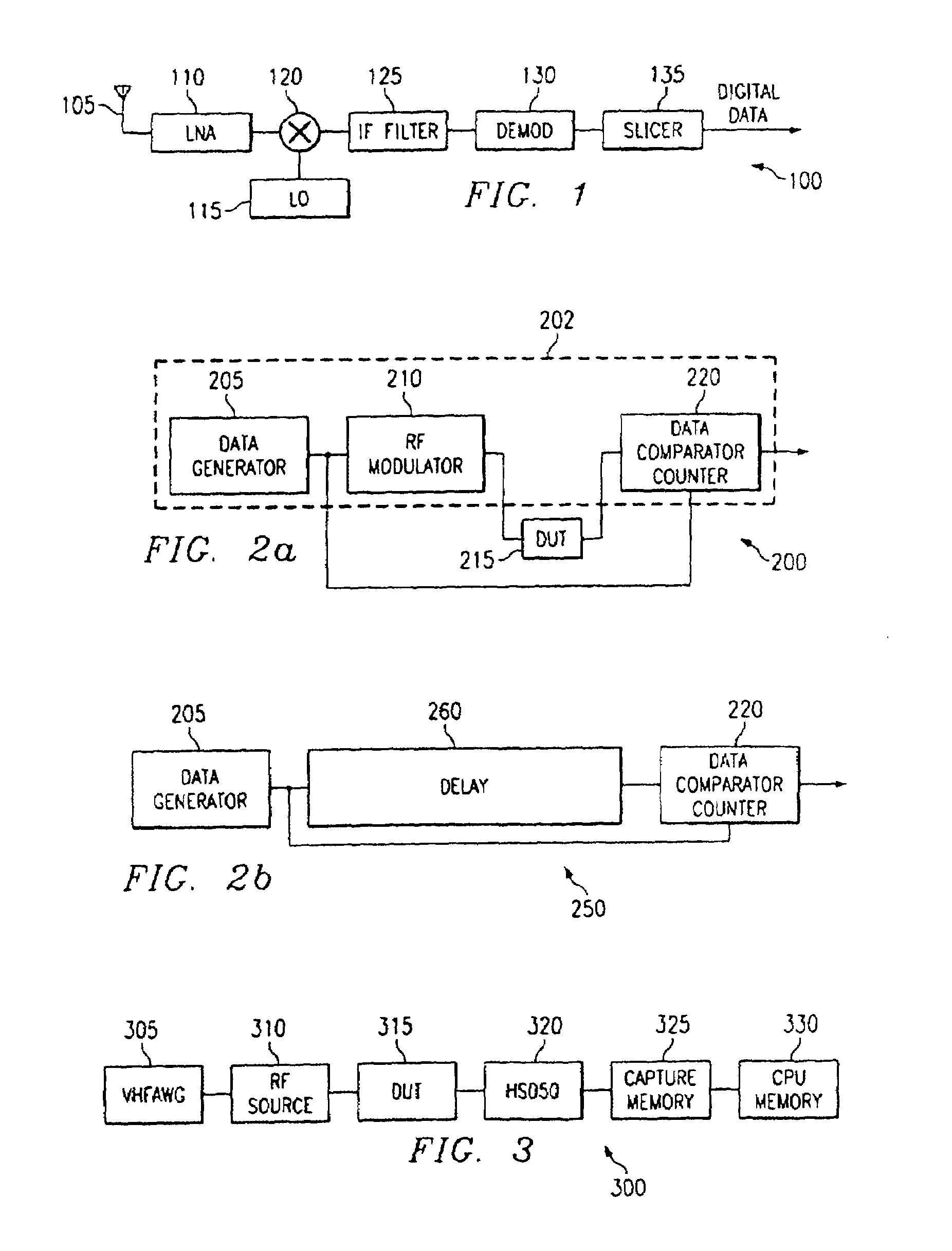
[0024]Referring now to FIG. 1, a block diagram illustrates an exemplary signal receive path 100 of a wireless device. The receive path 100 of a wireless device is responsible for receiving a wirelessly transmitted signal and converting it into a form that is ready for processing by the wireless device. Traditionally, wireless devices have used radio frequency (RF) signals for transmission. However, many of today's wireless devices are using microwaves, light beams, and laser beams. For discussion purposes, the wireless devices in these specifications will be limited to using RF signals, a...


PUM


Abstract

A bit-error-rate (BER) test is a crucial test for wireless devices to pass, since a device with a high BER does not perform at its best. BER tests are both costly and difficult to perform due to a delay incurred by the device under test (DUT) 215 and the testing hardware that is variable in nature. Because the delay is variable, a hardware BER test that can compensate for the delay is difficult to build and a software BER test that can easily compensate for the delay is very slow. The present invention provides a method and apparatus that can compensate for the variable delay. By doing so, a hardware BER test, which is considerably faster than a software BER test, is easily implemented.

Description

FIELD OF THE INVENTION[0001]This invention relates generally to digital testing, and particularly, testing bit-error-rates in digital communications systems.BACKGROUND OF THE INVENTION[0002]Digital testing is a necessary component of the manufacturing of digital devices. Testing helps in ensure the functionality of devices while it reduces the probability of shipping faulty products, which would result in a return and reduction in customer satisfaction. As a result, digital testing is performed on almost all digital devices. While digital testing is a necessary step of the manufacturing process, it is in general slow. Therefore, testing can add a significant amount of time and expense to the manufacture of a digital device.[0003]A seemingly ubiquitous device in today's world is a wireless communications device. From cellular telephones, cordless phones, wireless communications and data networks, pagers, etc., wireless devices have become a part of everyone's way of life. For these w...

Claims


Application Information

Patent Timeline
Patent Type & Authority Patents(United States)
IPC IPC(8): H04B1/10G01R27/28G06F11/00G01R31/317G01R31/3193H04L1/24H04L7/04
CPCG01R31/3171H04L1/24H04L7/04G01R31/3193
Inventor TARNG, TONY
Owner TEXAS INSTR INC
Why Eureka
Try Eureka