Hybrid Single Loop Feedback Retiming Circuit

Active Publication Date: 2019-07-18
CALIFORNIA INST OF TECH
View PDF8 Cites 3 Cited by
  • Summary
  • Abstract
  • Description
  • Claims
  • Application Information

AI Technical Summary

Benefits of technology

The present invention relates to a retiming circuit that includes a delay locked-loop (DLL) with a phase / frequency detector, a charge pump, a variable delay line, and a controlled delay line. The DLL generates an internal clock signal by delaying the reference clock signal using the variable delay line and the output clock signal. The controlled delay line causes the internal clock signal to be delayed by a delay cell, which then generates the output clock signal. The delay locked-loop includes an overflow detector and a reset circuit for selecting the appropriate delay cell. The method of retiming an output clock signal involves detecting the difference between the phase / frequency of the output clock signal and the reference clock signal, increasing or decreasing the voltage to cause a variable delay in the reference clock signal, and delaying the internal clock signal using the fixed delay cells in response to the voltage. The technical effect of the invention is to provide a more accurate and reliable output clock signal with improved stability and reliability.

Problems solved by technology

One major challenge with the scalable phased array architecture shown in FIGS. 1A and 1B is maintaining the timing accuracy of the reference clock signal in the distribution process.
One clock distribution technique, commonly referred to as a central star distribution technique, is impractical in large arrays as the number of traces and load amount become prohibitive.
Another clock distribution technique, commonly referred to as a daisy chained distribution technique, suffers from large timing variations due to variations in the supply voltage, temperature, and the loads.

Method used


Image

  • Hybrid Single Loop Feedback Retiming Circuit
  • Hybrid Single Loop Feedback Retiming Circuit
  • Hybrid Single Loop Feedback Retiming Circuit

Examples


Embodiment Construction

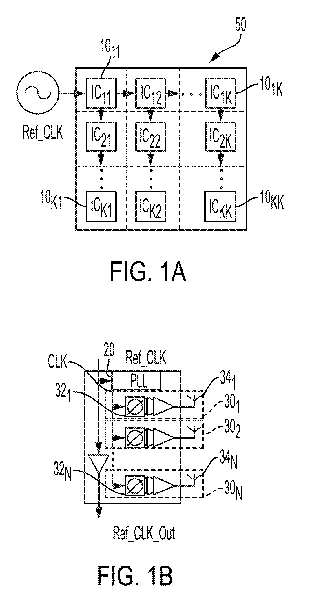
[0032]In accordance with one embodiment of the present invention, a hybrid single-loop (HSL) delay locked-loop (DLL) circuit generates a clock used in a phased array transmitter, phased array receiver or any other circuit that can benefit from an accurate, low-noise clock characterized by sub-picosecond root mean squared (RMS) jitter. A relatively large portion of the out-of-band phase noise of a DLL, in accordance with embodiments of the present invention, when the DLL is used in a phased array (or any other circuit) that includes an on-chip phase locked-loop (PLL), is rejected by the PLL, thus improving the overall performance of the array,

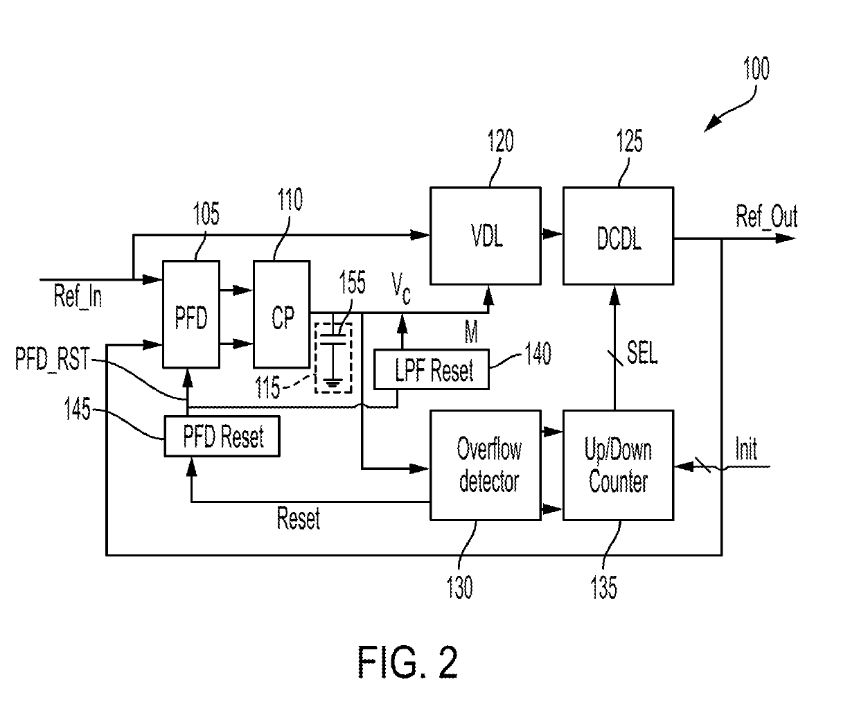
[0033]FIG. 2 is a simplified high-level block diagram of a DLL 100, in accordance with one embodiment of the present invention. DLL 100 is shown as including, in part, a phase / frequency detector (PDF) 105, a charge pump (CP) 110, low-pass filter (LPF) 115, a variable delay line (VDL) 120, a digitally controlled delay line (DCDL) 125, an overflow...


PUM


Abstract

A delay locked-loop includes, in part, a phase / frequency detector responsive to a reference clock signal, a charge pump responsive to the phase / frequency detector, a variable delay line responsive to an output of the charge pump to cause a delay in the reference clock signal thereby to generate an internal clock signal, and a controlled delay line that includes a multitude of fixed delay cells. The controlled delay line causes the internal clock signal to be delayed by a delay across one of the multitude of fixed delay cells in response to the output of the charge pump. The controlled delay line generates the output clock signal of the delay-locked loop. The delay locked-loop may further include an overflow detector configured to cause the selection of one of the multitude of fixed delays in response to the output of the charge pump.

Description

CROSS REFERENCE TO RELATED APPLICATIONS[0001]The present application claims benefit under 35 USC 119(e) of U.S. Application Ser. No. 62 / 616,947 filed Jan. 12, 2018, the content of which is incorporated herein by reference in its entirety.FIELD OF THE INVENTION[0002]The present invention is related to retiming circuits, and more particularly, to a delay-locked loop circuit.BACKGROUND OF THE INVENTION[0003]Phased arrays have experienced monotonic increase in usage since their inception and continue to be extensively employed in radar, sensing, and communication systems. Their directivity, signal-to-noise ratio (SNR), signal-to-interference ratio (SIR), and electronic beam stirring capability improves with increasing number of transmit / receive or antenna elements. Therefore very large-scale phased arrays, sometimes referred to as millions-element arrays, are desirable.[0004]Forming such a large array, however, requires a broad range of architectural and technological improvements, such...

Claims


Application Information

Patent Timeline
IPC IPC(8): G06F1/10H03L7/08H03L7/097H03L7/083
CPCG06F1/10H03L7/0805H03L7/097H03L7/083H03L7/07H03L7/0814H03L7/0816H03L7/0818H03L7/104
Inventor GAL, MATANHAJIMIRI, SEYED ALI
Owner CALIFORNIA INST OF TECH
Why Eureka
Try Eureka