Auto-ignition timing control and calibration method

Inactive Publication Date: 2006-07-11
MA THOMAS TSOI HEI
View PDF4 Cites 76 Cited by
  • Summary
  • Abstract
  • Description
  • Claims
  • Application Information

AI Technical Summary

Benefits of technology

[0013]In calculating the compression temperature trajectory of the cylinder charge with time, the initial and boundary conditions of the cylinder charge and the interim heat exchange processes preferably include engine speed and load, engine effective compression ratio, fuel composition, fuel / air mixture ratio, fuel injection and evaporation, intake charge quantity and temperature, coolant temperature, EGR quantity and temperature, residual charge quantity and temperature, each measured or inferred using appropriate sensors. This will be based on computer modelling of the thermodynamic processes influencing the compression temperature of the charge during the compression stroke and take into account all the interactions of the initial and boundary control parameters according to thermodynamic laws, thus capturing the effects of all these parameters in a unified manner in a characteristic compression temperature trajectory. In this way, the calibration process could be simplified to a small number of in-cycle characteristic parameters which are much closer to the ignition event than the myriad of control parameters at the initial condition, and can be readily adapted for use in a high level control map explicitly for auto-ignition timing. This would bypass the traditional method of calibrating each of the engine operating parameters at the initial and boundary conditions separately in a myriad of multi-layer multi-dimensional calibration maps, and thus reduce the calibration effort to a manageable level.
[0015]Thus according to the preferred method of the present invention where the effective compression ratio of the engine is one of the prescribed engine operating parameters, in order to determine and set the effective 
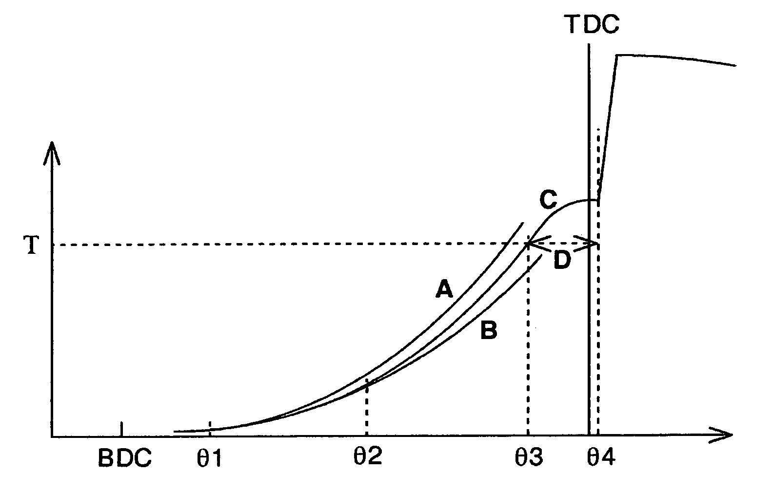
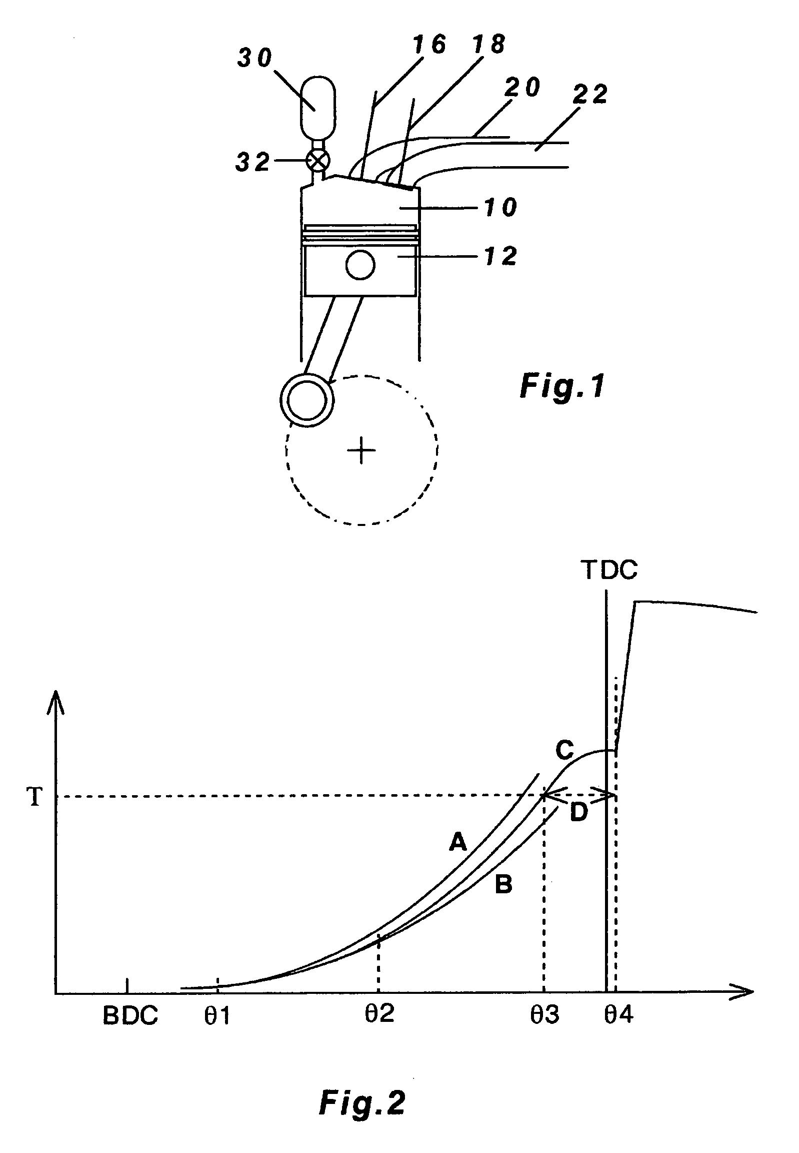
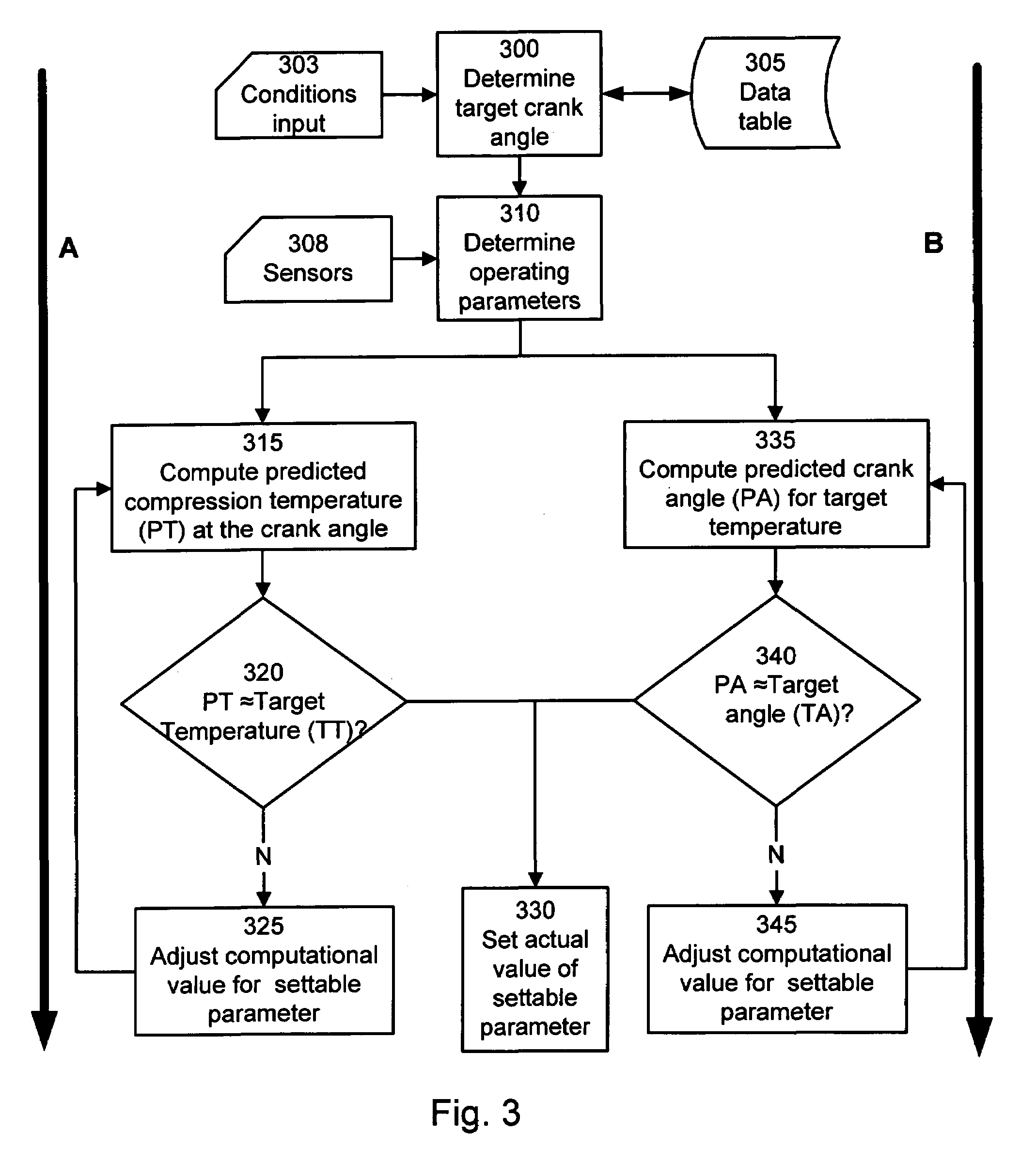
compression ratio to achieve the said target auto-ignition timing according to the said predetermined auto-ignition timing calibration map (or look-up table), two or more effective compression ratio setting values are used for calculating for each setting value the associated compression temperature trajectory, and the best setting value is found iteratively by interpolation or extrapolation between the said calculated trajectories that would produce a compression temperature trajectory reaching the said target temperature at the said target reference timing associated with the said target auto-ignition timing. In this way, a precise command setting of the compression ratio could be defined that would directly trigger a predictable and precise auto-ignition timing according to the said predetermined auto-ignition timing map.
[0017]As a further refinement while the invention is in use, a sensor measuring the start of combustion (start of rapid heat release) may be additionally provided for validating and if necessary adjusting the calibrated value of the above defined delay duration, thereby adaptively improving gradually with time the control accuracy of the auto-ignition timing in future operations.
[0019]It would be clear from the above that a small change in the target auto-ignition timing does not always imply a small unidirectional change in the compression ratio of the engine. In fact, the correlation could be non-linear and strongly influenced by the many parameters mentioned earlier in addition to the compression ratio, so that the required change in the final command setting of the compression ratio can only be determined by iterative calculations, taking into account the effects of many other engine operating parameters prevailing at the time including air charge temperature, fuel evaporation temperature, coolant temperature, residuals gas temperature, air fuel ratio, residuals quantity etc, all affecting the compression temperature trajectory. This is especially influential when the engine is being switched from the conventional SI or CI mode to the CAI / HCCI mode which may take place under a wide variety of engine operating conditions prevailing at the time of switching, for which the auto-ignition timing control method of the present invention ideally arrive at the correct optimum compression ratio setting immediately and explicitly for the first switched cycle to CAI / HCCI mode without misfire or knock.
[0021]In contrast, the auto-ignition timing control method of the present invention relies on high speed calculation prior to the combustion to arrive iteratively at an ignition conditioning parameter, namely, a target temperature occurring at a target reference timing, that will produce the desired auto-ignition timing for each stand-alone cycle before ignition actually happens. Such predictive approach is an improved method that can produce the correct auto-ignition timing to initiate the very first switched cycle to CAI / HCCI under any engine operating condition prevailing at the time of switching, and continue with the same control for each and every subsequent cycle without relying on any combustion feedback data being available.

Problems solved by technology

Other parameters such as fuel / air mixture ratio, intake charge quantity and temperature, residual charge quantity and temperature may also be used as the prescribed engine operating parameter or combination of parameters, but these may have slower response and at the same time may affect engine load, which could increase the calibration and control complexity.

Method used


Image

  • Auto-ignition timing control and calibration method
  • Auto-ignition timing control and calibration method
  • Auto-ignition timing control and calibration method

Examples


Embodiment Construction

[0044]FIG. 1 shows a schematic view of a cylinder 10 of a reciprocating internal combustion four-stroke cycle engine with a piston 12 reciprocating in the cylinder 10. Exhaust and intake valves 16, 18 connecting the cylinder 10 with exhaust and intake ports 20, 22 are shown in their closed positions during the compression and expansion strokes of the piston 12. The engine also includes a fuel system and an ignition system which are not shown in FIG. 1.

[0045]An auxiliary chamber 30 is connected by a shut-off valve 32 to the engine cylinder 10. The shut-off valve 32 is switched open and shut by an electro-magnetic, electro-hydraulic or electro-pneumatic actuator (not shown), connecting and disconnecting the auxiliary chamber 30 with the engine cylinder 10 at the various switching timings during the compression period of the engine, thus varying the effective compression ratio of the engine.

[0046]When the auxiliary chamber 30 is connected to the cylinder 10, its volume in conjunction w...


PUM


Abstract

An auto-ignition timing control and calibration method for use in an internal combustion engine having more than one ignition modes including the mode of compression ignition of a premixed fuel / air mixture (CAI / HCCI), wherein when the engine is operating in the CAI / HCCI mode, in order to determine a prescribed setting or combination of settings of engine operating parameters necessary to achieve a target auto-ignition timing according to a predetermined auto-ignition timing map, the associated compression temperature trajectory of the cylinder charge with time, calculated in dependence on the initial and boundary conditions of the said charge subjected to the said prescribed setting or combination of settings of the said engine operating parameters, and further in dependence on the interim heat exchange processes affecting the said charge, is used for testing and verifying that the said trajectory reaches a target temperature at a target reference timing relative to TDC of the engine, and wherein the said target temperature and timing are predetermined by calibration.

Description

FIELD OF THE INVENTION[0001]The present invention relates to a method for controlling the operating conditions for auto-ignition in an internal combustion engine so that the auto-ignition timing may be set accurately.BACKGROUND OF THE INVENTION[0002]A unique combustion process, referred to by various generic names such as premixed charge compression ignition (PCCI), homogeneous charge compression ignition (HCCI), or controlled auto-ignition (CAI), has been the subject of intensive research because of potential advantages of high efficiency, near-zero NOx emission and extremely low smoke pollution. It is also a common-mode combustion process which could be used advantageously in both types of the conventional internal combustion engine, namely, the gasoline spark ignition (SI) engine and the diesel compression ignition (CI) engine. However, there are several technical problems related to the use of the above combustion process in automotive applications. Firstly, it is difficult to c...

Claims


Application Information

Patent Timeline
IPC IPC(8): F02D41/34G06F19/00
CPCF02D15/04F02D35/026F02D35/028F02D41/3035F02D35/025F02B1/12F02B21/00F02D13/0276Y02T10/128Y02T10/12
Inventor MA, THOMAS TSOI HEI
Owner MA THOMAS TSOI HEI
Why Eureka
Try Eureka