
Electrosurgery with cooled electrodes

a technology of electrodes and electrodes, applied in the field of electrocardiography with cooled electrodes, can solve the problems of adding thermal inertia to the device, negatively affecting the penetration depth of the thermal effect, and the temperature of the heat pipe, so as to achieve less heat, less expensive, and less heat dissipation

Inactive Publication Date: 2006-07-11
ETHICON ENDO SURGERY INC
View PDF38 Cites 386 Cited by
  • Summary
  • Abstract
  • Description
  • Claims
  • Application Information

AI Technical Summary

Benefits of technology

[0012]It has been determined that for certain heat pipe diameters and lengths, the heat pipe itself can store and transfer sufficient heat to the environment, without the use of an additional heat sink, to maintain its temperature below the required 80° C.
[0013]There are several advantages to using the heat pipe to dissipate heat, rather than using a heat sink. First, elimination of the heat sink makes the device more compact, less expensive and therefore practical for sale. Second, the ideal electrosurgical pencil device would operate between 60 and 80° C. The lower temperature is the initiation of coagulation and the upper temperature is the sticking point. The addition of the heat sink lowers the operating temperature of the heat pipe which can negatively affect the depth of penetration of the thermal effect. If the pencil tip is too cold, then there may be a delay in the onset of coagulation and the effect of the coagulation will be deeper in the tissue than may be desired. The present invention passively controls the temperature of the pencil so that the temperature remains closer to the desired set point. Also, the addition of a heat sink adds thermal inertia to the device. This slows the rise time of the heat pipe temperature and also slows the drop in temperature after energy application is stopped. Both of these situations are undesirable. Removal of heat sink removes the thermal inertia.

Problems solved by technology

The addition of the heat sink lowers the operating temperature of the heat pipe which can negatively affect the depth of penetration of the thermal effect.
Also, the addition of a heat sink adds thermal inertia to the device.
This slows the rise time of the heat pipe temperature and also slows the drop in temperature after energy application is stopped.
Both of these situations are undesirable.

Method used


Image

  • Electrosurgery with cooled electrodes
  • Electrosurgery with cooled electrodes
  • Electrosurgery with cooled electrodes

Examples


Embodiment Construction

[0027]A description of preferred embodiments of the invention follows.

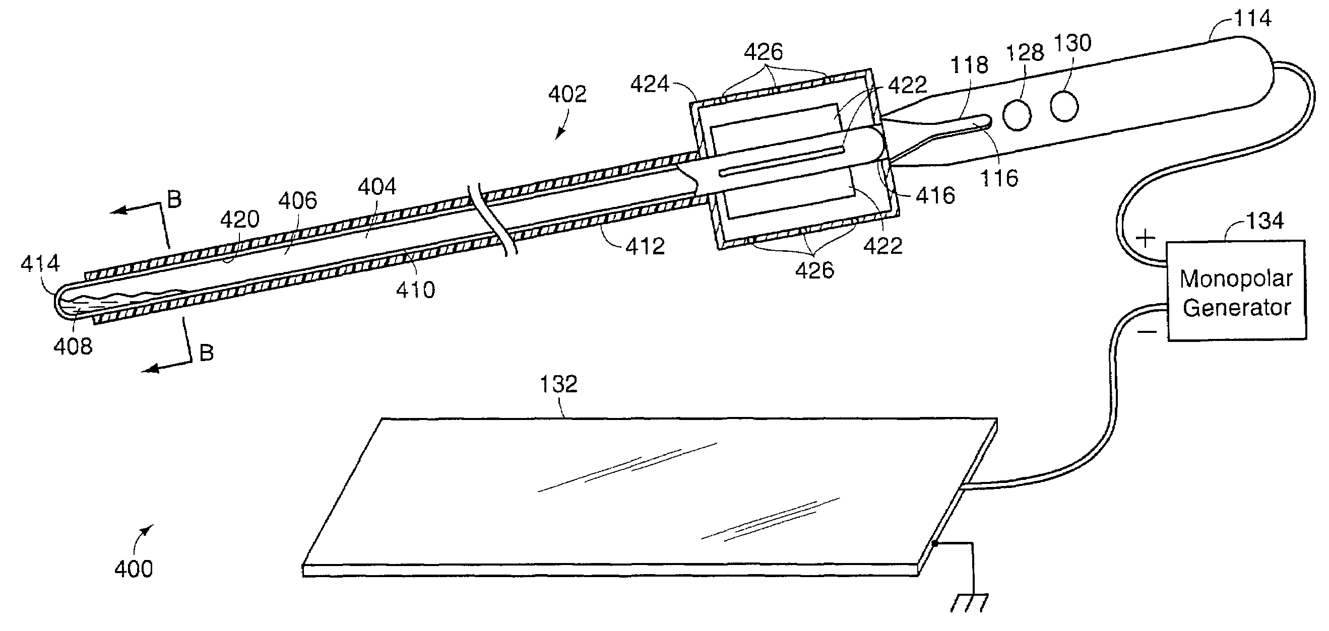
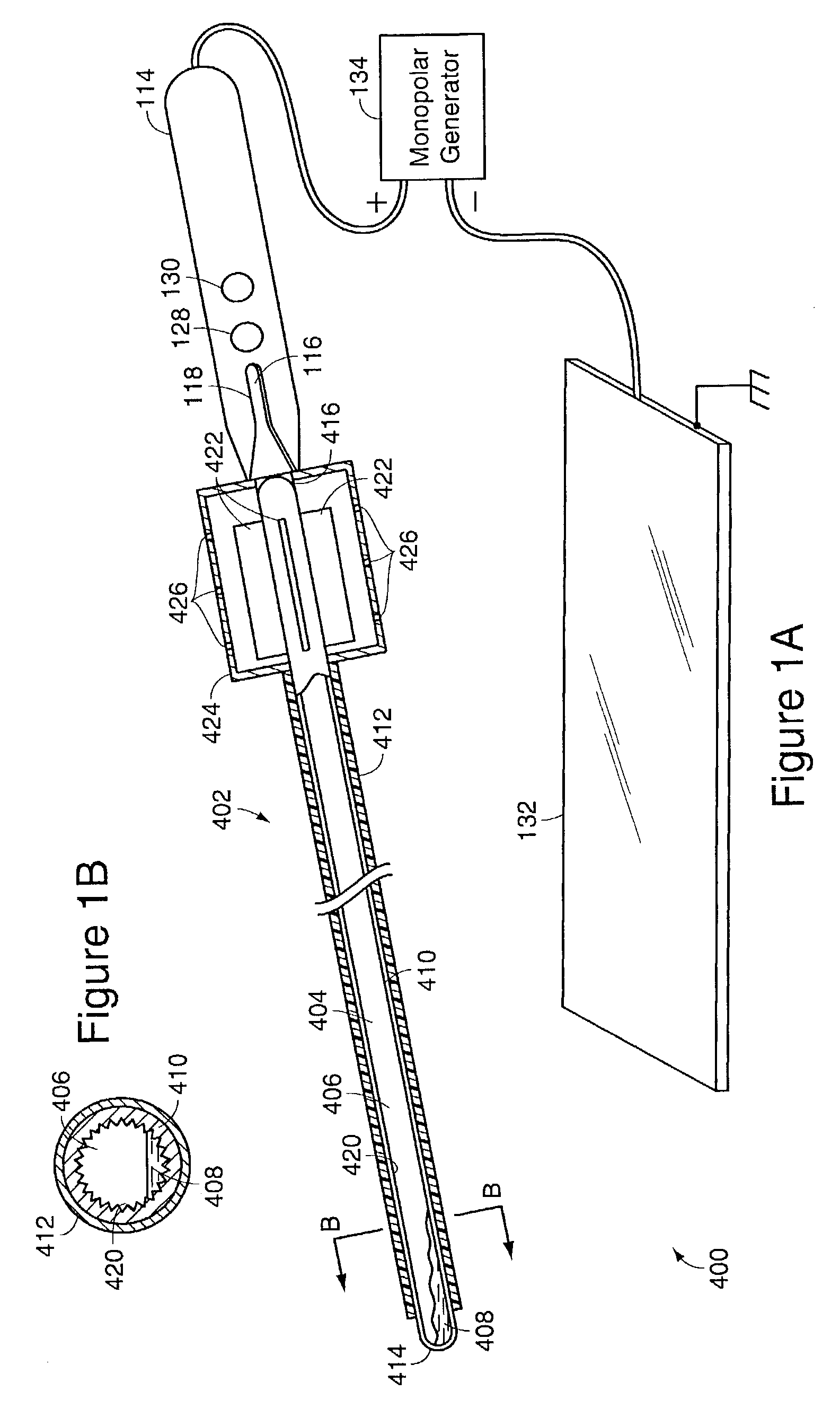
[0028]FIGS. 1A and 1B schematically depict an embodiment of a monopolar electrosurgical system 400 in accordance with the present invention. In this embodiment, the monopolar probe 402 employs a heat pipe heat transfer device 404 as the monopolar electrode. The heat pipe is a well-known heat transfer mechanism and is described in textbooks on heat transfer such as Heat Transfer, Fourth Edition, by J. P. Holman, McGraw-Hill, 1963, pp. 464–467, which is incorporated herein in its entirety by reference. FIG. 1B is a schematic cross-sectional view of the monopolar probe 402 taken along line B—B of FIG. 1A.

[0029]Referring to FIGS. 1A and 1B, the heat pipe 404 includes an internal cavity 406 which is sealed at both ends. The cavity 406 is partially evacuated and contains a heat transfer fluid such as water 408. The outer shell 410 is made of a conductive metallic material such as copper. The shell 410 is covered over mo...


PUM


Abstract

A cooled electrosurgical system includes an electrosurgical device having at least one electrode for applying electrical energy to tissue. In one embodiment, the electrode includes an internal cavity in which a cooling medium such as water is contained. The internal cavity is closed at both ends of the device such that the cooling medium is contained within the electrode at the surgical site such that the cooling medium does not contact the tissue being treated. The electrosurgical device has an electrode and a heat pipe to conduct heat from the electrodes where substantially all heat conducted from the electrode through the heat pipe is dissipated along the length of the heat pipe. The heat pipe can have a thermal time constant less than 60 seconds and preferably less than 30 seconds.

Description

RELATED APPLICATIONS[0001]This application is a continuation of Ser. No. 09 / 780,028, filed Feb. 9, 2001, now U.S. Pat. No. 6,544,264, which is a continuation-in-part of application Ser. No. 09 / 702,006, filed Oct. 30, 2000, now U.S. Pat. No. 6,503,248, and a continuation-in-part of application Ser. No. 09 / 516,089 filed Mar. 1, 2000, now U.S. Pat. No. 6,206,876, which is a continuation of application Ser. No. 08 / 892,008, filed Jul. 14, 1997, now U.S. Pat. No. 6,074,389, which is a divisional of Ser. No. 08 / 402,881, filed Mar. 10, 1995, now U.S. Pat. No. 5,647,871. The entire teachings of the above applications are incorporated herein by reference.BACKGROUND OF THE INVENTION[0002]Electrosurgery is commonly used to cauterize, cut and / or coagulate tissue. In typical electrosurgical devices, RF electrical energy is applied to the tissue being treated. Local heating of the tissue occurs, and, depending upon the waveform of the applied energy and the electrode geometry, the desired effect i...

Claims


Application Information

Patent Timeline
Patent Type & Authority Patents(United States)
IPC IPC(8): A61B18/14A61B18/00
CPCA61B18/1402A61B18/1442A61B2018/126A61B2018/00023A61B2018/1253A61B2018/00005
Inventor LEVINE, ANDY H.MEADE, JOHN C.LICHTMAN, PHILIP R.
Owner ETHICON ENDO SURGERY INC
Learn More