
Exhaust back pressure sensor using absolute micromachined pressure sense die

a technology of absolute pressure sense die and back pressure sensor, which is applied in the direction of machines/engines, instruments, exhaust treatment electric control, etc., can solve the problems that the configuration of conventional absolute pressure sensor lacks the ability to process pressure and temperature signals from more than one absolute sense di

Active Publication Date: 2006-07-11
HONEYWELL INT INC
View PDF19 Cites 55 Cited by
  • Summary
  • Abstract
  • Description
  • Claims
  • Application Information

AI Technical Summary

Problems solved by technology

The problem with such conventional geometric absolute pressure sensor arrangements and relationships is that the wire bond pads and active regions of the sense die end up facing the sensed media.
Additionally, conventional absolute pressure sensor configurations lack the ability to process pressure and temperature signals from more than one absolute sense die.

Method used


Image

  • Exhaust back pressure sensor using absolute micromachined pressure sense die
  • Exhaust back pressure sensor using absolute micromachined pressure sense die
  • Exhaust back pressure sensor using absolute micromachined pressure sense die

Examples


second embodiment

[0049]The second embodiment relates to an absolute and differential pressure sensor with isolation between the sensor's electronics and the sensed media. The sensor's electronic circuitry can incorporate a specific integrated circuit (ASIC) that processes and outputs the signal for both absolute and differential measurements. Such a sensor can be utilized for exhaust gas recirculation (EGR) systems on automotive gasoline engines.

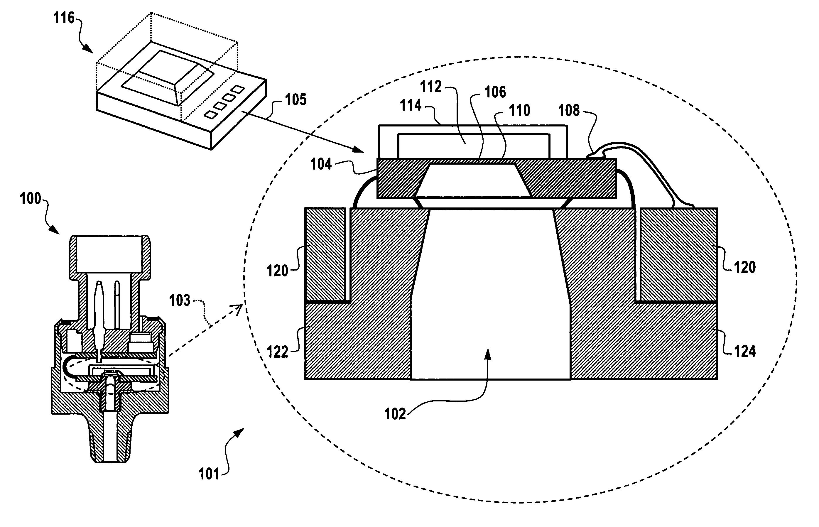
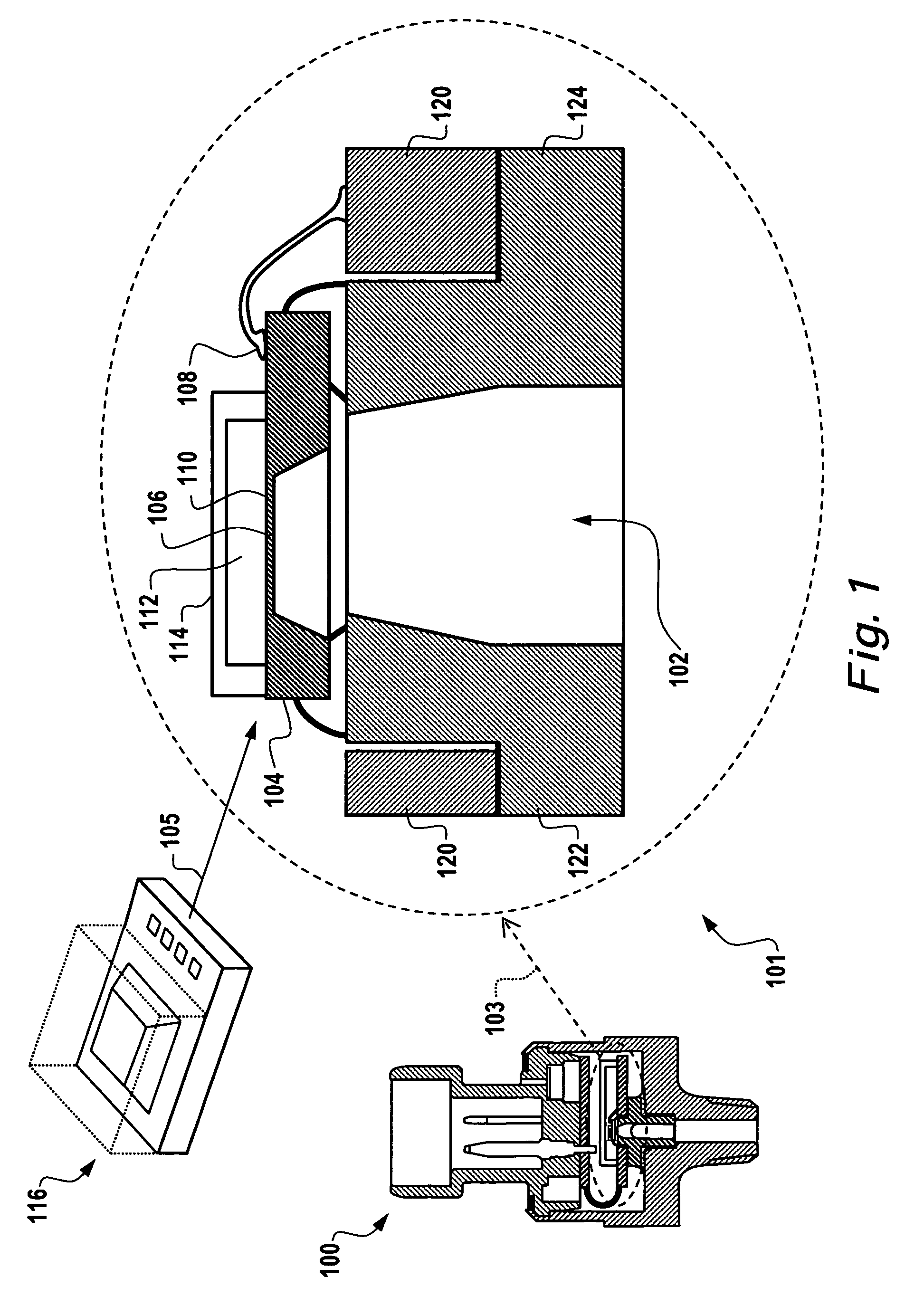
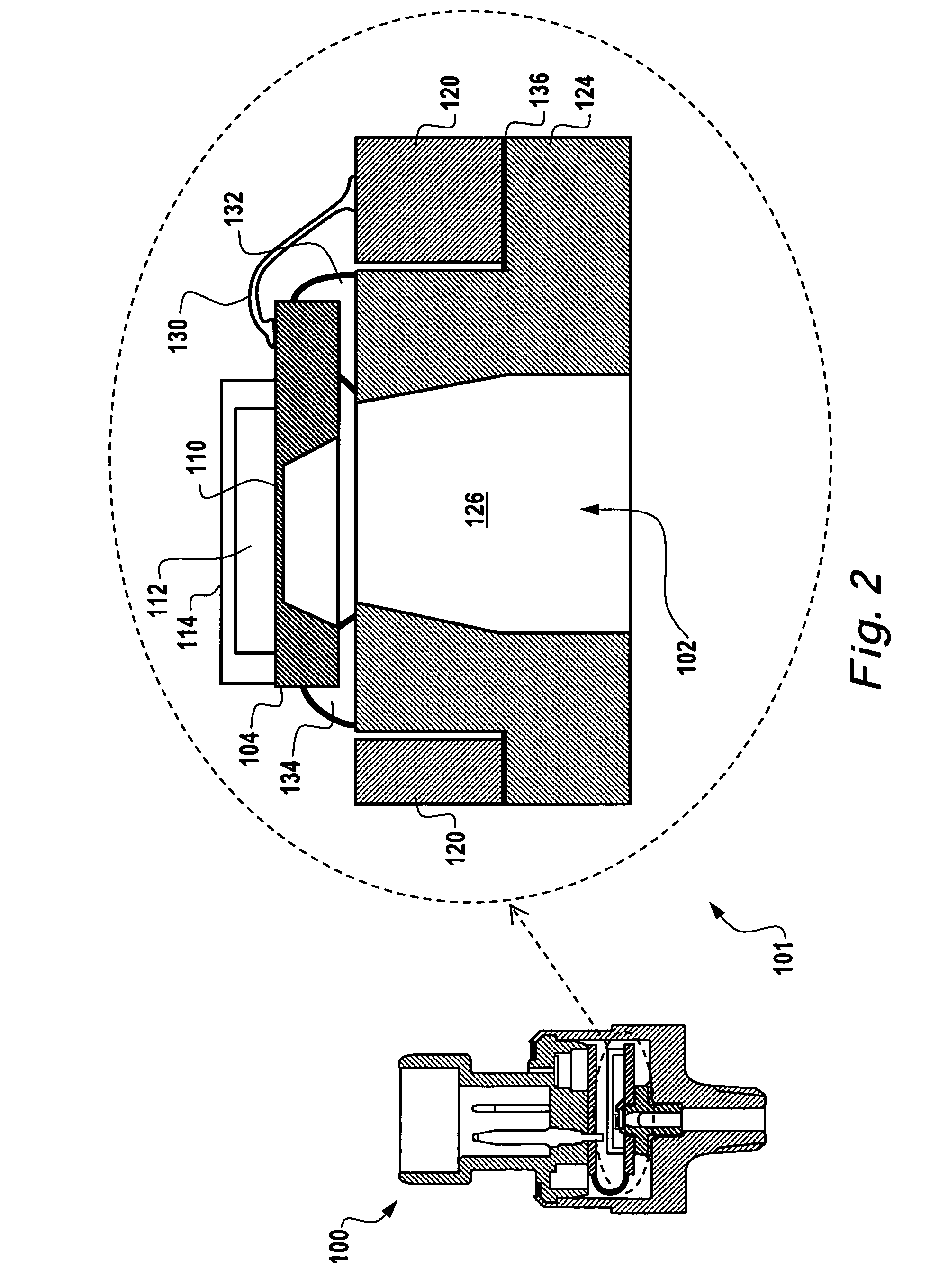
[0050]The embodiment of FIG. 5 is based upon the use of absolute pressure sense die 104. The sense die 104 can be configured via micromachined silicon with piezoresistors in a Wheatstone bridge configuration and a topside glass cap. Wire bond pads on the topside allow for electrical connection to the Wheatstone bridge. The sense die 104 can be mounted to a plastic carrier using, for example, a silicone adhesive. The adhesive can be cured and the assembly can be leak checked.

[0051]Two sense die / carrier assemblies can be attached to a printed circuit board (PC...

third embodiment

[0070]Because known acids and chemicals contained in the sensed media do not attack this gel 1112, 1114, this side of the die 1107, 1109 can also be protected from acids and chemical attacks. Products implemented via the third embodiment discussed herein sense pressure from the backside of two dies 1107, 1109. Associated circuitries can provide EMC protection, over-voltage and reverse polarity protection and other algorithms utilizing a single ASIC. Products based on conventional configurations, however, sense pressure on both sides of a single die.

[0071]FIG. 12 illustrates a block diagram of a two-ASIC circuit system 1200, which can be implemented in accordance with an alternative embodiment. System 1200 generally includes an over-voltage and polarity protection circuit 1202 whose output is coupled to a high port ASIC 1206 and a reference port ASIC 1204. The Output from the high port ASIC 1206 can be coupled to a differential circuit 1208, which in turn is coupled to a pressure pul...


PUM


Abstract

Sensor systems and methods are disclosed, which generally incorporate isolation between the sensor's electronics and the sensed media. The sensor's electronic circuit can incorporate one or more application specific integrated circuit (ASIC) that processes and outputs the signal for both absolute and differential measurements. Such a sensor can be adapted for use in exhaust gas re-circulation (EGR) systems utilized with automotive gasoline engines. Such a sensor can also be utilized for measuring differential pressure across diesel particular filters and / or applications in which differential pressure is required for system control and / or monitoring purposes. The absolute pressure sensor disclosed herein can therefore sense the exhaust pressure on automotive engines and other mechanical and / or electromechanical devices and machines.

Description

REFERENCE TO RELATED APPLICATION[0001]This patent application claims priority under 35 U.S.C. § 119(e) to provisional patent application Ser. No. 60 / 584,976 entitled “Pressure Sensor Methods and Systems,” which was filed on Jul. 2, 2004, the disclosure of which is incorporated herein by reference.TECHNICAL FIELD[0002]Embodiments are generally related to sensor methods and systems. Embodiments are also related to pressure sensors. Embodiments are additionally related to micromachined pressure sensors, including absolute pressure sensors that include sense die thereof. Embodiments also relate to exhaust back pressure sensors.BACKGROUND OF THE INVENTION[0003]Many micromachined absolute pressure sensors function by mounting the material removal side of the silicon sense die into glass. Such a methodology can create an absolute pressure sensor. In general, an absolute pressure sensor can employ a sealed volume of gas or vacuum on one side of a diaphragm, with another side of the diaphrag...

Claims


Application Information

Patent Timeline
Patent Type & Authority Patents(United States)
IPC IPC(8): G01M19/00G01M99/00
CPCF01N3/021F01N9/002G01L19/0038G01L19/147G01L27/005G01L9/0092G01L19/0627G01L19/143Y02T10/47Y02T10/20Y02T10/12Y02T10/40
Inventor PARKER, GREGORY D.MARCUS, PHILIP J.PHAM, TUYEN V.WESLEY, TRAVIS D.
Owner HONEYWELL INT INC
Learn More