
Method of making a biosensor

a biosensor and sensor technology, applied in the manufacture of diaphragms, electrical instruments, immobilised enzymes, etc., can solve the problems of affecting the quality of the resulting edge, the time-consuming and labor-intensive of the technique,

Inactive Publication Date: 2006-07-11
ROCHE DIABETES CARE INC +1
View PDF108 Cites 320 Cited by
  • Summary
  • Abstract
  • Description
  • Claims
  • Application Information

AI Technical Summary

Benefits of technology

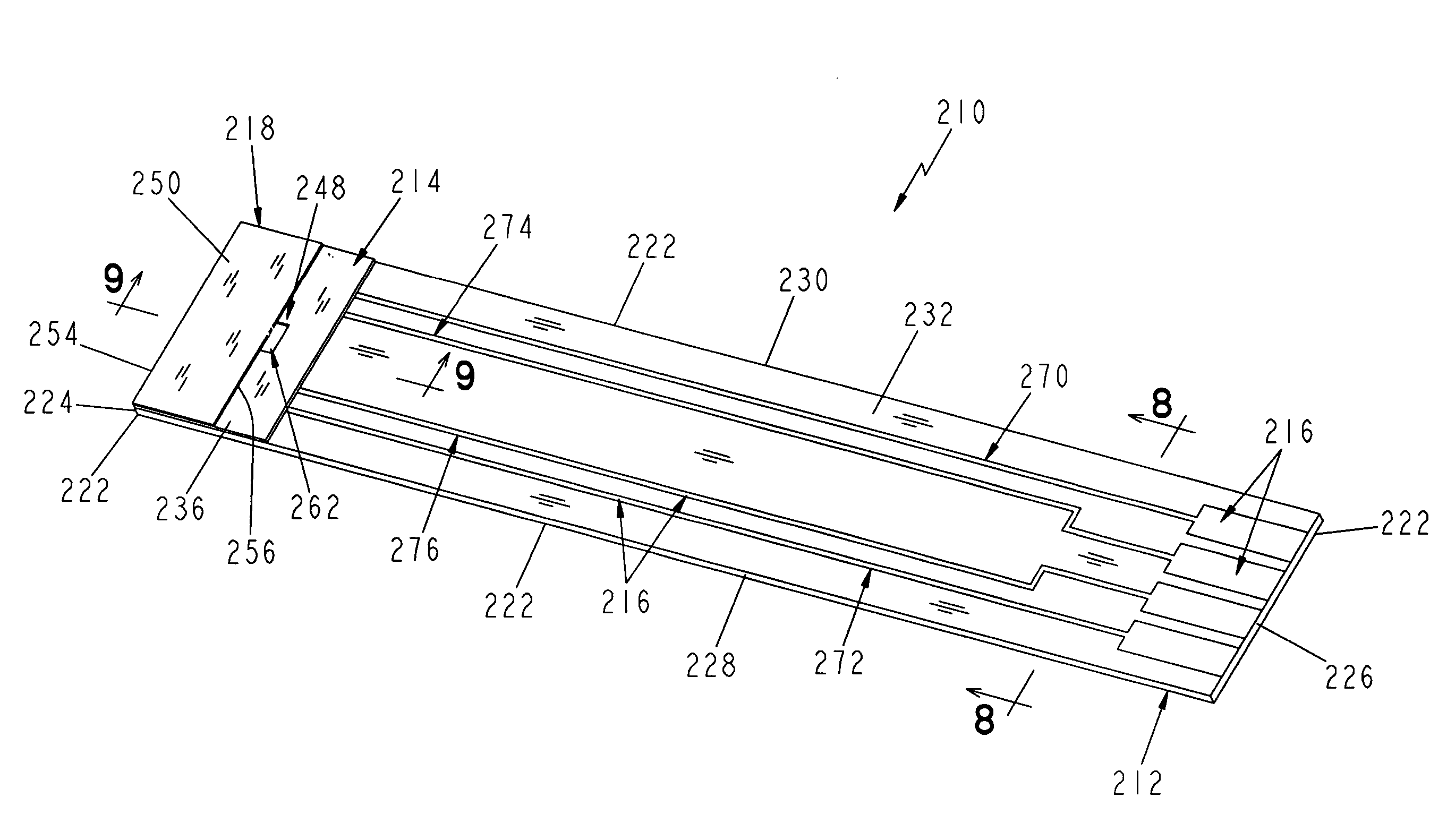
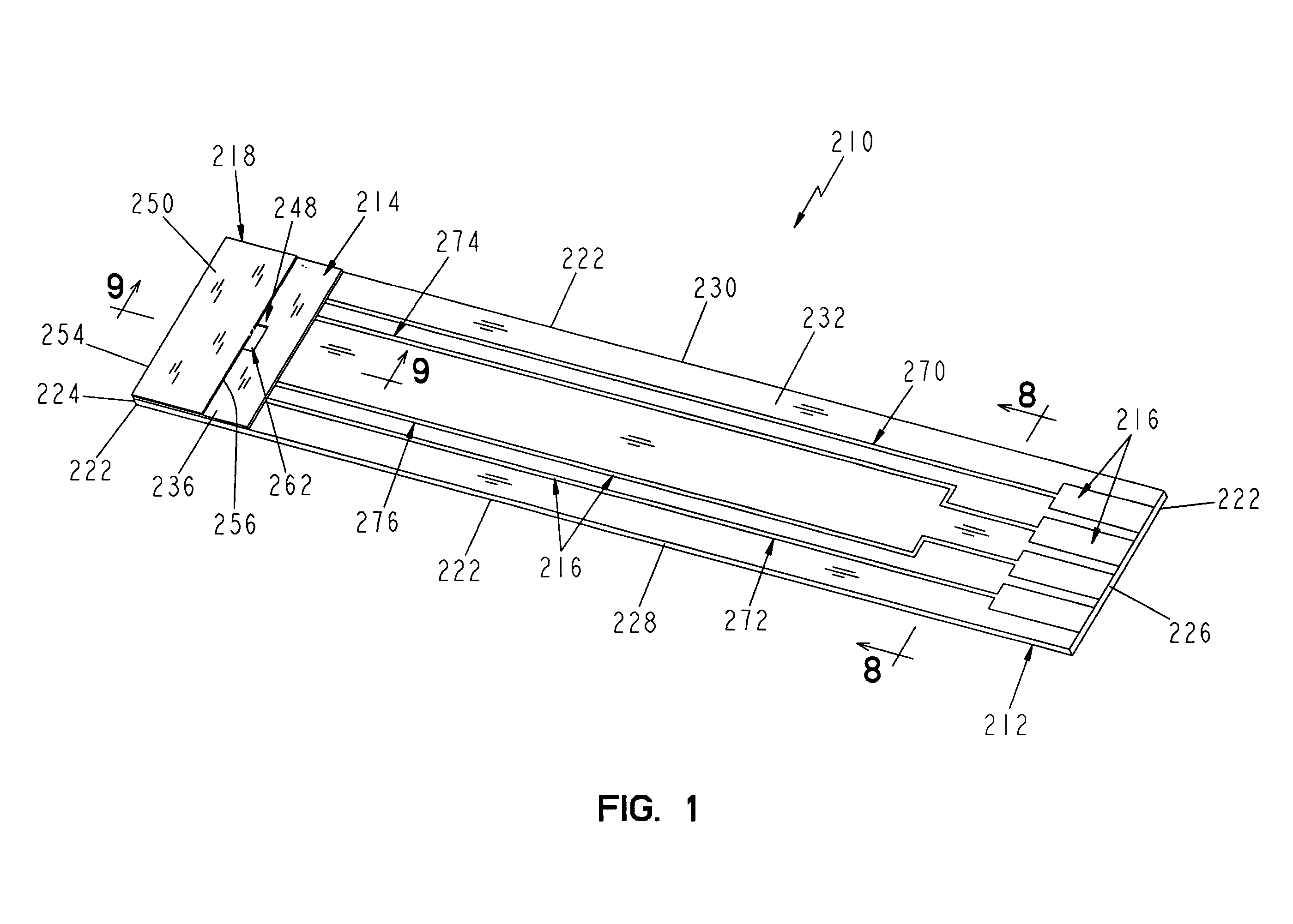
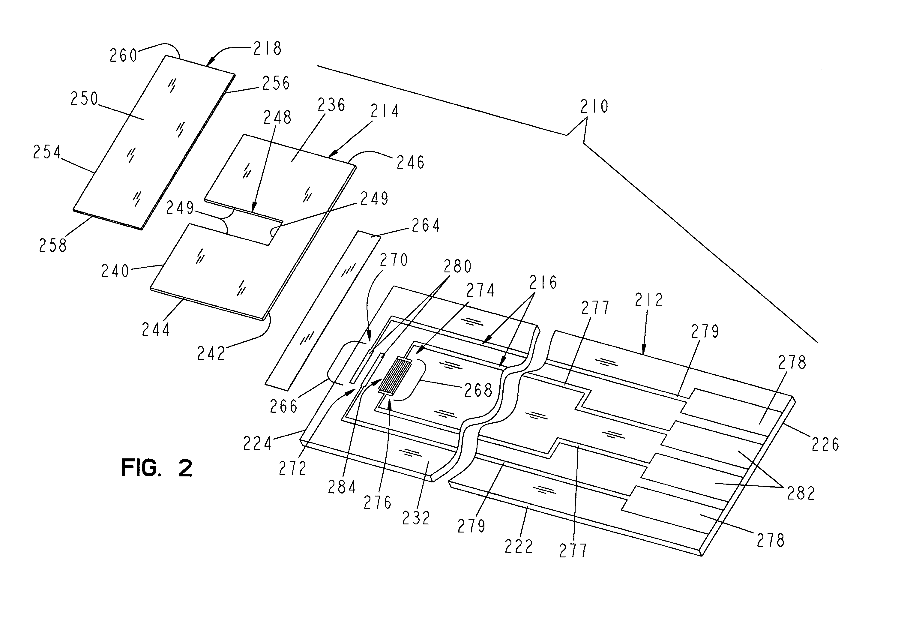
[0012]Still further, according to the present invention a method of making a biosensor is provided. The method comprises providing an electrically conductive material on a base and forming a pre-determined electrode pattern on the base using laser ablation through a mask, the mask having a mask field with at least one opaque region and at least one window formed to allow a laser beam to pass through the mask and to impact predetermined areas of the electrically conductive material.

Problems solved by technology

It is therefore appreciated that such a technique can be rather time consuming if a complex electrode pattern is to be formed on the surface.
Still further, it is appreciated that the precision of the resulting edge is rather limited.

Method used


Image

  • Method of making a biosensor
  • Method of making a biosensor
  • Method of making a biosensor

Examples


Embodiment Construction

[0065]For the purposes of promoting an understanding of the principles of the invention, reference will now be made to the embodiments illustrated in the drawings, and specific language will be used to describe the embodiments. It will nevertheless be understood that no limitation of the scope of the invention is intended. Alterations and modifications in the illustrated devices, and further applications of the principles of the invention as illustrated therein, as would normally occur to one skilled in the art to which the invention relates are contemplated, are desired to be protected.

[0066]A biosensor in accordance with the present invention provides a surface with electrode patterns formed thereon, the electrode patterns preferably having a smooth edge quality. It is a particular aspect of the present invention that precise quality is obtained for the edges of the electrical components located on the biosensor. Having a smooth or high edge quality of the elements can contribute ...


PUM

PropertyMeasurementUnit
Lengthaaaaaaaaaa
Lengthaaaaaaaaaa
Lengthaaaaaaaaaa

Abstract

A method of making a biosensor is provided. The biosensor includes an electrically conductive material on a base and electrode patterns formed on the base, the patterns having different feature sizes. The conductive material is partially removed from the base using broad field laser ablation so that less than 90% of the conductive material remains on the base and that the electrode pattern has an edge extending between two points. A standard deviation of the edge from a line extending between two points is less than about 6 μm.

Description

CROSS-REFERENCE TO RELATED APPLICATIONS[0001]The present application is a Continuation-in-Part of U.S. application Ser. No. 09 / 411,940, filed Oct. 4, 1999 now U.S. Pat. No. 6,662,439; a Continuation-in-Part of U.S. application Ser. No. 09 / 684,257 filed Oct. 6, 2000 now U.S. Pat. No. 6,645,359; a Continuation in Part of U.S. patent application Ser. No. 09 / 840,843, filed Apr. 24, 2001 now U.S. Pat. No. 6,767,440; and a Continuation in Part of U.S. application Ser. No. 10 / 264,891, filed Oct. 4, 2002, each of which are hereby incorporated by reference in its entirety.FIELD OF THE INVENTION[0002]The present invention relates to a method of making a biosensor, more specifically a biosensor having electrode sets formed by laser ablation.BACKGROUND AND SUMMARY OF THE INVENTION[0003]Electrochemical biosensors are well known and have been used to determine the concentration of various analytes from biological samples, particularly from blood. Examples of such electrochemical biosensors are de...

Claims


Application Information

Patent Timeline
IPC IPC(8): G01R3/00B23K26/36C12Q1/00G01N27/30G01N27/403G01N33/487G01N33/49G01N33/543H05K1/00H05K3/02
CPCC12Q1/001G01N33/5438H05K3/027G01N27/3272H05K1/0393Y10T29/49117Y10T29/49156Y10T29/49155Y10T29/49007G01N27/30
Inventor BHULLAR, RAGHBIR S.DIEBOLD, ERIC R.HILL, BRIAN S.SURRIDGE, NIGEL A.WALLING, DOUGLAS P.
Owner ROCHE DIABETES CARE INC
Learn More