
Multi-component analyzing apparatus

a multi-component, analyzing apparatus technology, applied in the direction of material analysis, optical radiation measurement, instruments, etc., can solve the problems of destroying refrigerating apparatuses, deteriorating performance of refrigerating apparatuses, and requiring a firm destruction of fluorocarbons which cannot be recycled-used, so as to suppress mutual interference and improve precision

Inactive Publication Date: 2006-07-04
HORIBA LTD
View PDF23 Cites 5 Cited by
  • Summary
  • Abstract
  • Description
  • Claims
  • Application Information

AI Technical Summary

Benefits of technology

The present invention provides a multi-component analyzing apparatus that can improve calculation precision in each of component ratio calculations, even in the case of new / old mixed refrigerants used in refrigerating / air conditioning machines. The apparatus uses infrared light to measure the components, and a programmable calculator to analyze the infrared light intensity. The apparatus is capable of analyzing a plurality of refrigerant components with high precision, while mutual interference between them is minimized. The apparatus includes a calculation processing unit capable of solving simultaneous equations to accurately determine the concentrations of the components. The mutual interference correction terms used in the analysis allow for the accurate correction of interference adverse influences caused by overlapping of the components' absorption spectra. The apparatus is cost-effective and can analyze the concentration ratios of the components without being affected by the bandpass filters used in the detectors. The simultaneous equations used in the analysis have mutual interference correction terms that can be solved to accurately determine the concentrations of the components.

Problems solved by technology

Also, such fluorocarbon which cannot be recycling-used must be firmly destroyed.
On the other hand, in the case that a mixing ratio of collected fluorocarbon is not proper since fluorocarbon is collected in an erroneous manner, if this collected fluorocarbon is directly recycling-used, then there is a risk that performance of refrigerating apparatuss is deteriorated, or these refrigerating apparatuss are destroyed.
However, in the above-described conventional mixed-refrigerant analyzing apparatus, as represented in the below-mentioned table 2, measurement errors of the respective refrigerant components are very large.
More specifically, as to the fluorocarbon of R32 and R22, measurement error thereof are large.
As a result, the measuring precision of these refrigerant components R32 and R22 is mutually deteriorated.
However, since the above-described measurement values “y1” to “yn” acquired by the respective detectors are obtained in such a way that after such a infrared light having a predetermined wavelength range has been selectively penetrated by employing, for example, a plurality of optical filters among the infrared light which has passed through the measuring-subject sample, the respective detectors detect intensity of the infrared light which has passed through the respective optical filters, there is no way capable of avoiding such an event that several widths are produced in the wavelengths of the transmission light due to the filter characteristics of the optical filters.
As a result, such an adverse influence for distorting the filter characteristics of the above-explained optical filters is received by the infrared absorptions of other measuring-subject components mixed with each other, so that the absorbances which have been converted into the logarithms cannot become completely equal to such absorbances obtained by adding the absorbances to each other obtained by the respective measuring-subject components.
Thus, there are some possibilities that errors caused by the interference influences may occur in the measurement values “y1” to “yn” detected by the respective detectors.
Thus, even if the simultaneous equations as indicated in the formula (2) are solved, there are some possibilities that errors of several % happen to occur.
However, very recently, higher precision less than 1% is required for such multi-component analyzing apparatus capable of calculating concentration ratios of fluorocarbon, so that the conventional multi-component analyzing apparatus could not be suitably used in such higher precision.
Since a plurality of these measuring-subject components are mixed with each other in the preselected concentration, the measuring-subject components may mutually interfere with each other.
As a result, there is no way to avoid such a fact that errors are increased.

Method used


Image

  • Multi-component analyzing apparatus
  • Multi-component analyzing apparatus
  • Multi-component analyzing apparatus

Examples


first embodiment

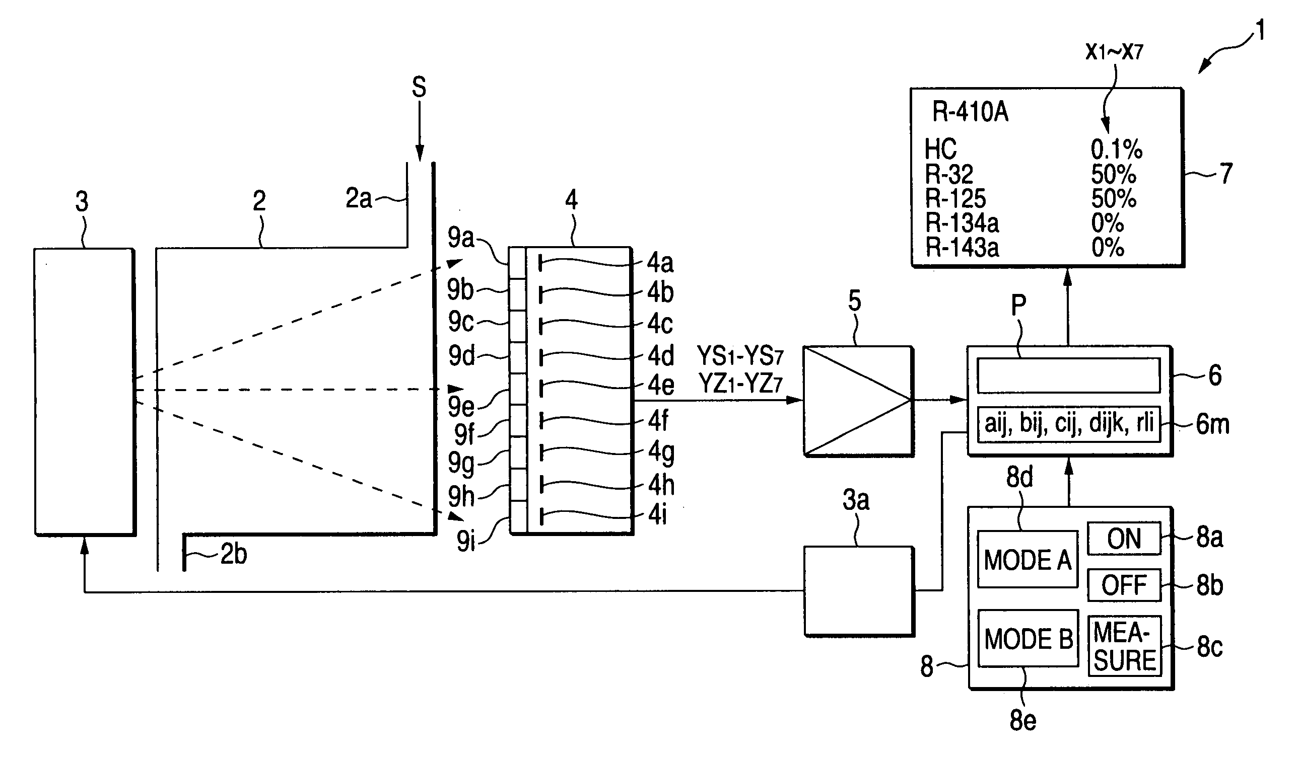
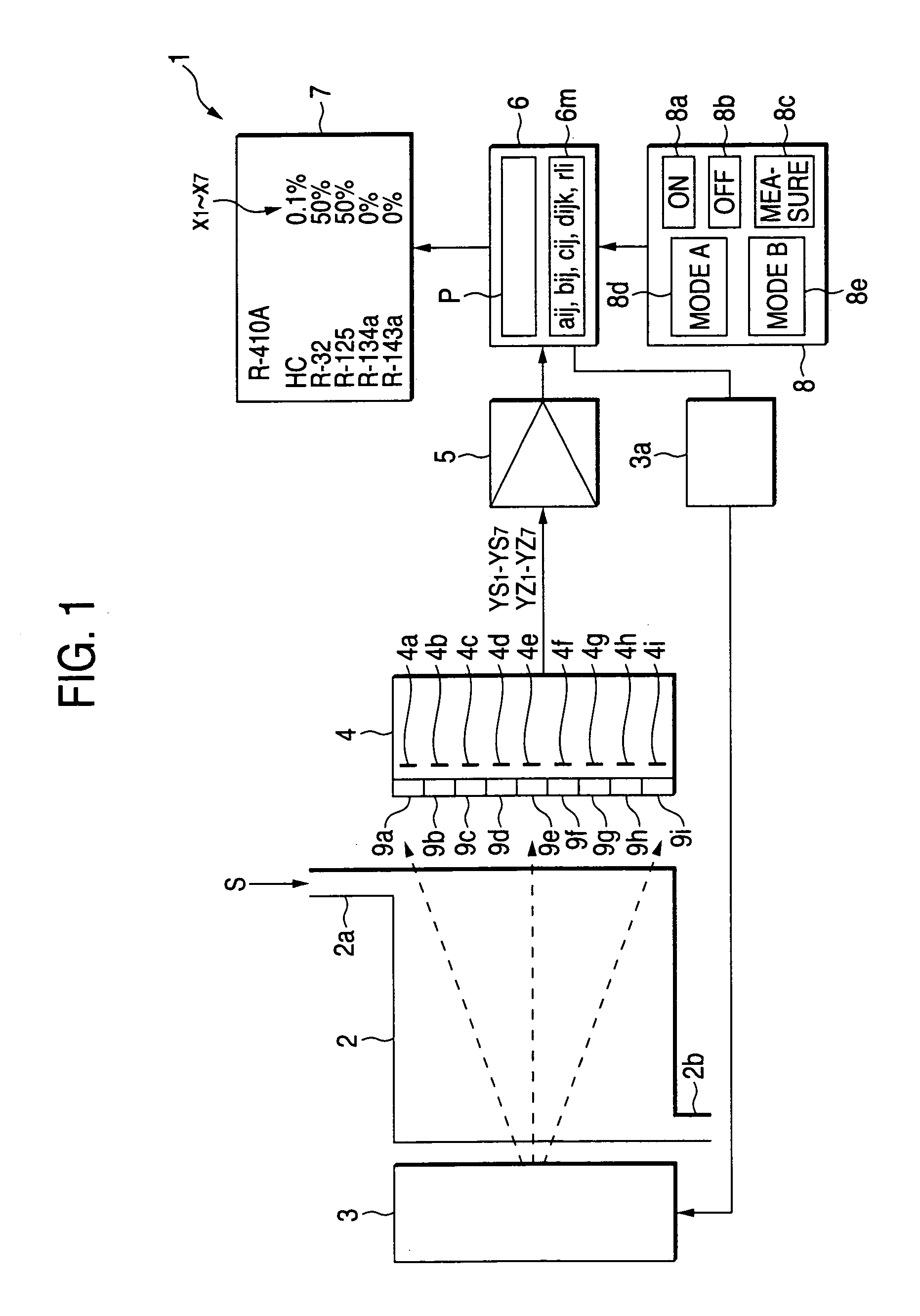
[0069]FIG. 1 is a schematic diagram for indicating an overall arrangement of a fluorocarbon concentration measuring apparatus functioning as an example of a multi-component analyzing apparatus according to the present invention. In FIG. 1, reference numeral 2 indicates a measuring cell used to conduct the fluorocarbon “S” which has been collected as one example of a measuring subject sample, and reference numeral 3 indicates an infrared light source for irradiating infrared light to the measuring cell 2. Also, reference numeral 4 indicates a detector for detecting transmission light of the infrared light, which has passed through the measuring cell 2. Reference numeral 5 shows an amplifier for amplifying a detection output from the detector 4. Reference numeral 6 represents a calculation processing unit which executes an analyzing process program “P” so as to perform an analyzing operation. In accordance with this analyzing process program P, intensity of transmission light amplifie...

second embodiment

[0131]Referring now to drawings, a mixed-refrigerant analyzing apparatus of the present invention will be described in detail. FIG. 14 to FIG. 16 indicates one embodiment mode of the present invention. First, FIG. 14 schematically shows a structural example of a mixed-refrigerant analyzing apparatus according to the present invention. In this drawing, reference numeral 101 shows Bombe which has stored thereinto a mixed refrigerant functioning as sample gas “S”, and reference numeral 102 represents a Bombe valve. Reference numeral 103 indicates a sample gas supplying path used to connect Bombe 101 to a mixed-refrigerant analyzing apparatus 105 (will be discussed later). This sample gas supplying path 103 is equipped with a pressure control device 104.

[0132]Reference numeral 105 shows a mixed-refrigerant analyzing apparatus 105. This mixed-refrigerant analyzing apparatus 105 is arranged as follows. That is, for instance, reference numerals 106 and 107 represent a gas inlet and a gas o...


PUM

PropertyMeasurementUnit
weightaaaaaaaaaa
weight %aaaaaaaaaa
wavelength rangesaaaaaaaaaa

Abstract

A multi-component analyzing apparatus in which infrared light is irradiated to a measuring-subject sample S which is constituted by either measuring-subject components whose sorts or quantities are limited or by a mixed article made of said measuring-subject components; intensity of infrared light having respective wavelength ranges which are fitted to infrared absorption spectra of the respective measuring-subject components among such infrared light penetrated through the measuring-subject sample S is measured by employing a plurality of detectors 4a to 4g corresponding thereto; and said multi-component analyzing apparatus is comprised of a calculation processing unit 6 for analyzing the infrared light intensity of the respective wavelength ranges so as to acquire concentration x1 to x7 of the respective measuring-subject components; wherein the calculation processing unit 6 is capable of executing an analyzing process program P for executing analysis operations of the concentration x1 to x7 of the respective measuring-subject components by solving simultaneous equations which are constituted by equations having mutual interference correction terms used to correct interference adverse influences occurred among the respective measuring-subject components.

Description

BACKGROUND OF THE INVENTION[0001]The present invention is related to a multi-component analyzing apparatus, particularly, to a mixed-refrigerant analyzing apparatus capable of analyzing refrigerant components contained in a mixed refrigerant in a separate manner.[0002]Generally speaking, so-called “fluorocarbon” is conventionally used as refrigerants which are employed in refrigerating apparatus (cooling machines) such as, refrigerators and air conditioners. As to fluorocarbon, there is an HFC series of new refrigerants in addition to a CFC series and an HCFC series of old refrigerants. These series of fluorocarbon own various problems as to destruction of the ozone layer, and global warming trends in earth temperatures, so that there are duties to collect and recycling-use the above-described fluorocarbon. Also, such fluorocarbon which cannot be recycling-used must be firmly destroyed.[0003]On the other hand, the fluorocarbon of R410A, R407C, R404A, and R507A which is typically kno...

Claims


Application Information

Patent Timeline
Patent Type & Authority Patents(United States)
IPC IPC(8): G01N21/35
CPCG01N21/3504
Inventor NOMURA, TOSHIYUKIKOHSAKA, HIROJIKOJIMA, KENNOSUKEASANO, ICHIROMATSUMOTO, NAOYUKI
Owner HORIBA LTD
Learn More