
Self-drilling, self-anchoring fastener for concrete

a self-drilling, concrete technology, applied in the direction of fastening devices, screws, secure devices, etc., can solve the problems of reducing the material cost, and requiring a large amount of labor

Inactive Publication Date: 2006-07-04
SIMPSON STRONG TIE
View PDF63 Cites 51 Cited by
  • Summary
  • Abstract
  • Description
  • Claims
  • Application Information

AI Technical Summary

Benefits of technology

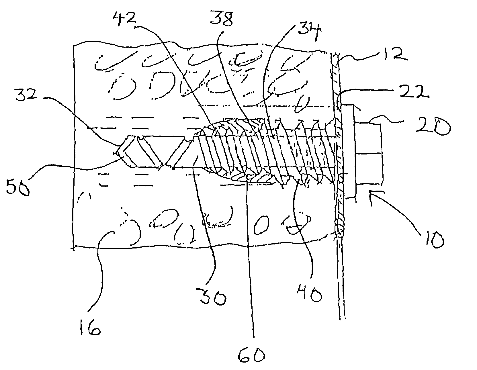
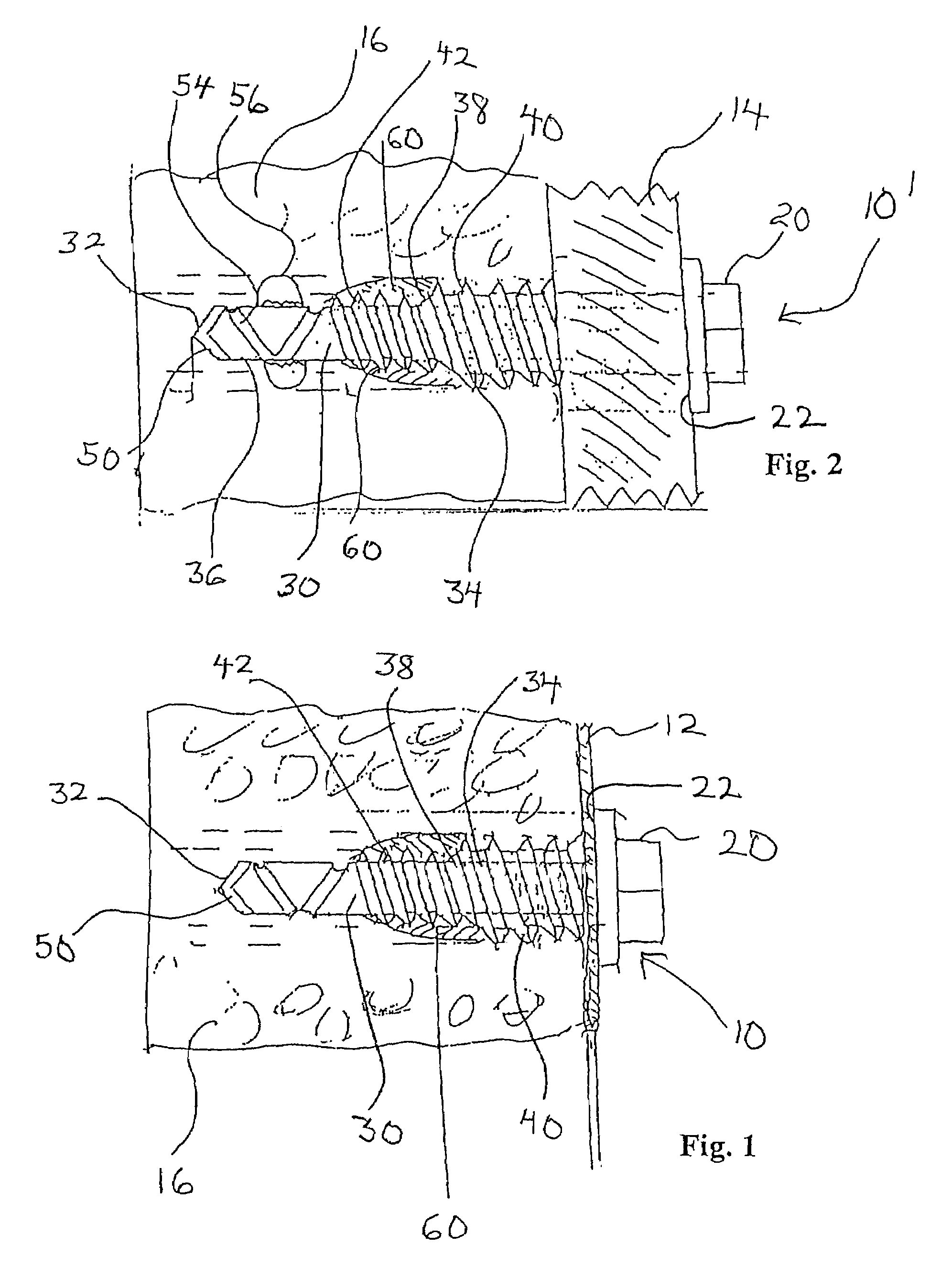
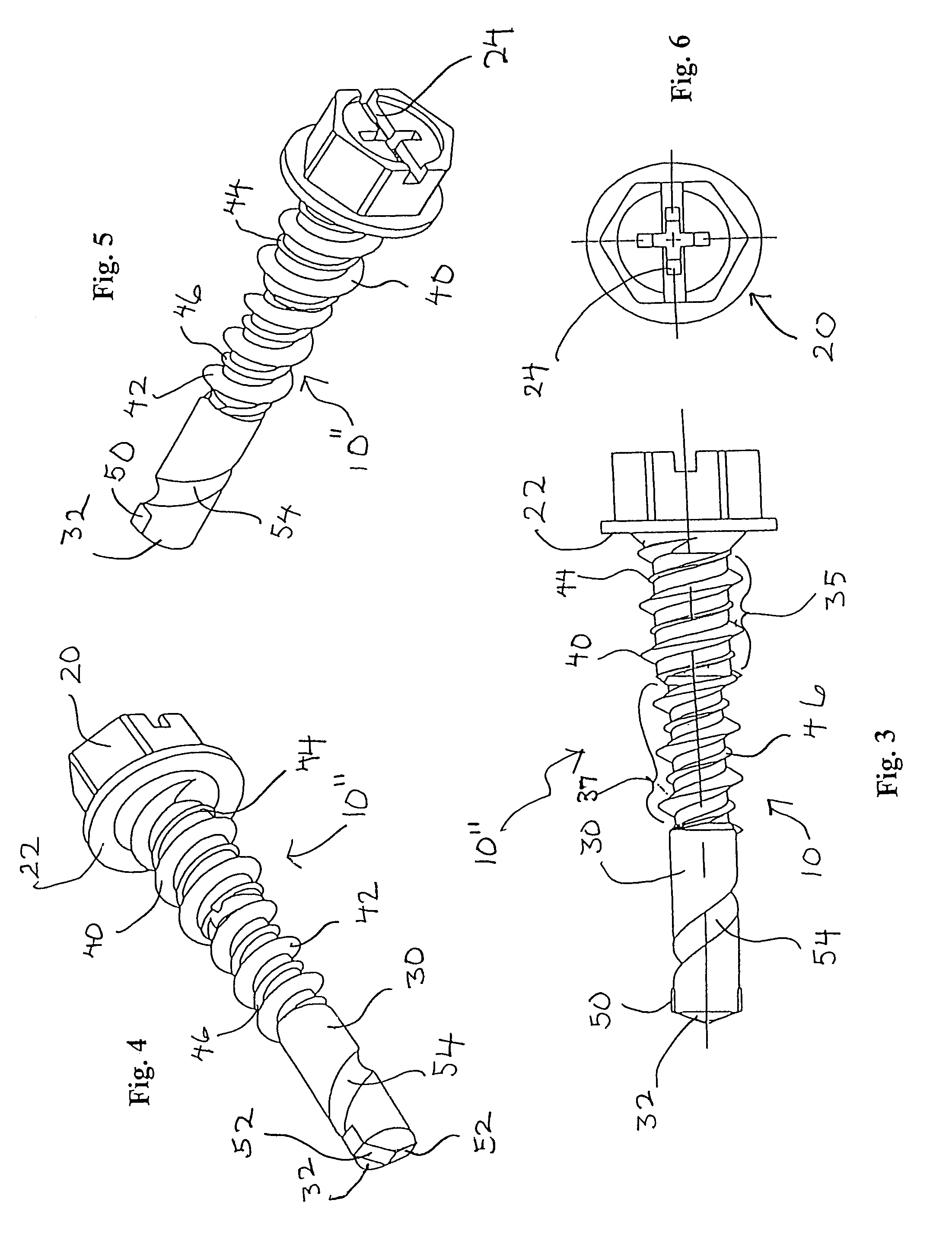
The invention is a fastener for fastening an object, such as an electrical panel box, to a masonry-like structure. The fastener includes a head with a radially extending engagement surface for engagement with the panel box. A shank axially extends from the engagement surface and has a distal end with a self-drilling tip. The shank also has a threaded portion with a first and second thread. The fastener can be used with an adhesive or a polymer coating for increased resistance to loosening. The technical effects of the invention include improved fastening speed, durability, and resistance to damage from drilling and material transfer.

Problems solved by technology

Additionally, such devices require pre-drilling of the hole into which the stud anchor is located, thereby complicating installation.
Removeability of the anchor stud, when desired, is also a major problem when using these devices.
The requirements involve considerable labor costs that must be added to the material cost.

Method used


Image

  • Self-drilling, self-anchoring fastener for concrete
  • Self-drilling, self-anchoring fastener for concrete
  • Self-drilling, self-anchoring fastener for concrete

Examples


example i

[0055]In one example, a 1⅞″ fastener with a hexhead was drilled into a 1¼″ wall of a standard concrete block. The patch had a 30% by volume nylon filler, and no adhesive or epoxy with microheads or other substance was applied to the lower portion of the shank. The break-loose torque was measured at approximately 45 ins-lbs. The 360° torque was measured at approximately 30 ins-lbs. The residual torque was measured at approximately 25 ins-lbs.

example ii

[0056]In a second example, the fastener was configured substantially identical to the Example I fastener except a coating consisting of epoxy with microcaps was applied to the lower end of the shank. The fastener was drilled into the concrete block substantially similar to the fastener installation of Example I. The break-loose torque was measured to be approximately 125 ins-lbs., the 360° torque was approximately 85 ins-lbs., and the residual torque was approximately 70 ins-lbs.

example iii

[0057]In a third example, a fastener was configured substantially identical to that of Example II except the coating employed 50% nylon filler in addition to the epoxy with the microcaps. The fastener was drilled into the 1¼″ wall of the concrete block substantially similar to the fasteners of Examples I and II. The break-loose torque was measured to be approximately 50 ins-lbs., a 360° torque was measured to be approximately 35 ins-lbs., and a residual torque was measured to be approximately 35 ins-lbs.

[0058]It was observed for Examples I, II and III that the concrete powder which formed when installing the fastener in the concrete block was not trapped by the resin patch but apparently was guided around the patch and migrated to the surface of the concrete block.


PUM


Abstract

A fastener adapted for anchoring into a masonry structure, such as a concrete block, employs an epoxy resin system so that the fastener is both mechanically engaged and bonded to the structure. In one preferred configuration, the bead is composed of a hardener, a resin and a nylon powder and has a cardioid-shaped configuration which subtends substantially 360° around the shank at an intermediate position of a threaded portion of the fastener. Various configurations are disclosed, including a fastener wherein adhesive in microencapsulated form is also applied to a lower intermediate portion. In addition, wings may extend from the shank.

Description

CROSS-REFERENCE TO RELATED APPLICATION[0001]This application claims the priority of U.S. Provisional Application No. 60 / 170,689 filed on Dec. 14, 1999.BACKGROUND OF THE INVENTION[0002]This invention relates generally to fasteners which anchor an object to a support structure. More particularly, the present invention relates to fasteners which are designed to secure an object to a masonry structure.[0003]In the attachment of panels, supports, channels or other devices to a masonry-like structure, it is commonplace to utilize a stud anchor which incorporates a wedging mechanism. Such devices frequently require a manipulation of the wedge to properly set the device within the bore and will also require a secondary fastener member, such as a nut, to be placed over the workpiece and tightened on the stud. Additionally, such devices require pre-drilling of the hole into which the stud anchor is located, thereby complicating installation. Removeability of the anchor stud, when desired, is ...

Claims


Application Information

Patent Timeline
Patent Type & Authority Patents(United States)
IPC IPC(8): F16B25/10F16B33/06F16B35/02
CPCF16B11/006F16B25/0026F16B25/0052F16B25/0089F16B25/103F16B25/0068Y10S411/93
Inventor TOBACK, ALEX S.
Owner SIMPSON STRONG TIE
Learn More