
Atmospheric pressure ion lens for generating a larger and more stable ion flux

Inactive Publication Date: 2006-06-27
THE UNIV OF BRITISH COLUMBIA
View PDF26 Cites 3 Cited by
  • Summary
  • Abstract
  • Description
  • Claims
  • Application Information

AI Technical Summary

Benefits of technology

[0017]The present invention focuses on improving ion transmission into a downstream device, such as a mass spectrometer, by focusing on the point at which the ions and charged droplets are initially generated. This is accomplished by situating at least one “ion lens” in close proximity to the sprayer tip of an ion source that is substantially at atmospheric pressure. In this document, “ion lens” or “ion focusing element” means an electrode that can be used to change the equipotentials in the atmospheric pressure region in order to cause more ions from the source to reach a downstream device such as a mass spectrometer. More particularly, the invention is concerned with an “ion lens” mounted adjacent a sprayer tip or a sprayer outlet, to change the equipotentials as defined. Various shapes of ion lenses may be incorporated into the ESI source to focus a larger number of ions into the orifice of the downstream mass spectrometer. By adding a single ion lens and applying a high voltage to the ion lens, an increase in the total count rate of all ions in the mass spectrum has been observed when a reduced flow-rate ESI source and an ionspray source operating at high flow-rates were used. In addition, the ion signal stability was improved for both ion sources. Furthermore, the fragmentation and charge state patterns of the ions produced can be advantageously optimized by varying the geometry of the ion lens (or ion lenses) and the magnitude of the potentials applied to the ion lens (or ion lenses).

Problems solved by technology

Unfortunately, the use of ESI and ionspray with mass spectrometers results in poor ion sampling efficiency.
Due to the substantial expense associated with vacuum pumps, a compromise must be reached between the desired aperture size and the cost of the vacuum pumps.
However, a larger vacuum pump will be required to maintain the same pressure within the mass spectrometer.
Unfortunately, increasing the vacuum pump speed results in a mass spectrometer with a substantially higher cost.
However, this is difficult because the ion spread is controlled by both equipotentials and gas velocity within the reduced pressure region or regions.
Also, if an inappropriate potential were applied to the lens elements, undesirable ion fragmentation may result.
Conversely, in an atmospheric pressure region, it is the equipotentials which dominate the ion trajectories and the distance that the ions travel between collisions is so short that the ions do not accumulate enough energy to effect ion fragmentation or to achieve significant velocity.
However, no evidence was given as to whether an appreciable increase in the ion signal was observed.
However, these lenses were located at a substantial distance from both the sprayer and the inlet aperture of the capillary that led to the transition region so it is questionable as to how much of a focusing effect the lenses in the source housing provided near the sprayer tip.
Furthermore, no results were shown to indicate that an increase in ion signal is achievable with this method.
However, the lenses used both AC and DC voltages which requires a more expensive power supply.
Furthermore, the Feng device cannot be used with a curtain gas, therefore the practical use is limited.
However, once again, the cylindrical electrode within the ESI source housing was far away from the ESI sprayer.
Furthermore, the configuration of the cylindrical electrode was fixed, and the position or orientation of the electrode could not be adjusted.
Bertsch also taught that their device was applicable for flow rates of 1 μL / min up to 2 ml / min and thus was not applicable for reduced flow-rate ESI sources.

Method used


Image

  • Atmospheric pressure ion lens for generating a larger and more stable ion flux
  • Atmospheric pressure ion lens for generating a larger and more stable ion flux
  • Atmospheric pressure ion lens for generating a larger and more stable ion flux

Examples


Embodiment Construction

[0096]In this description, like elements in different figures will be represented by the same numerals. In addition, all voltages are DC voltages. Furthermore, all simulation results shown in this description were obtained using the MacSIMION, version 2.0 simulation program.

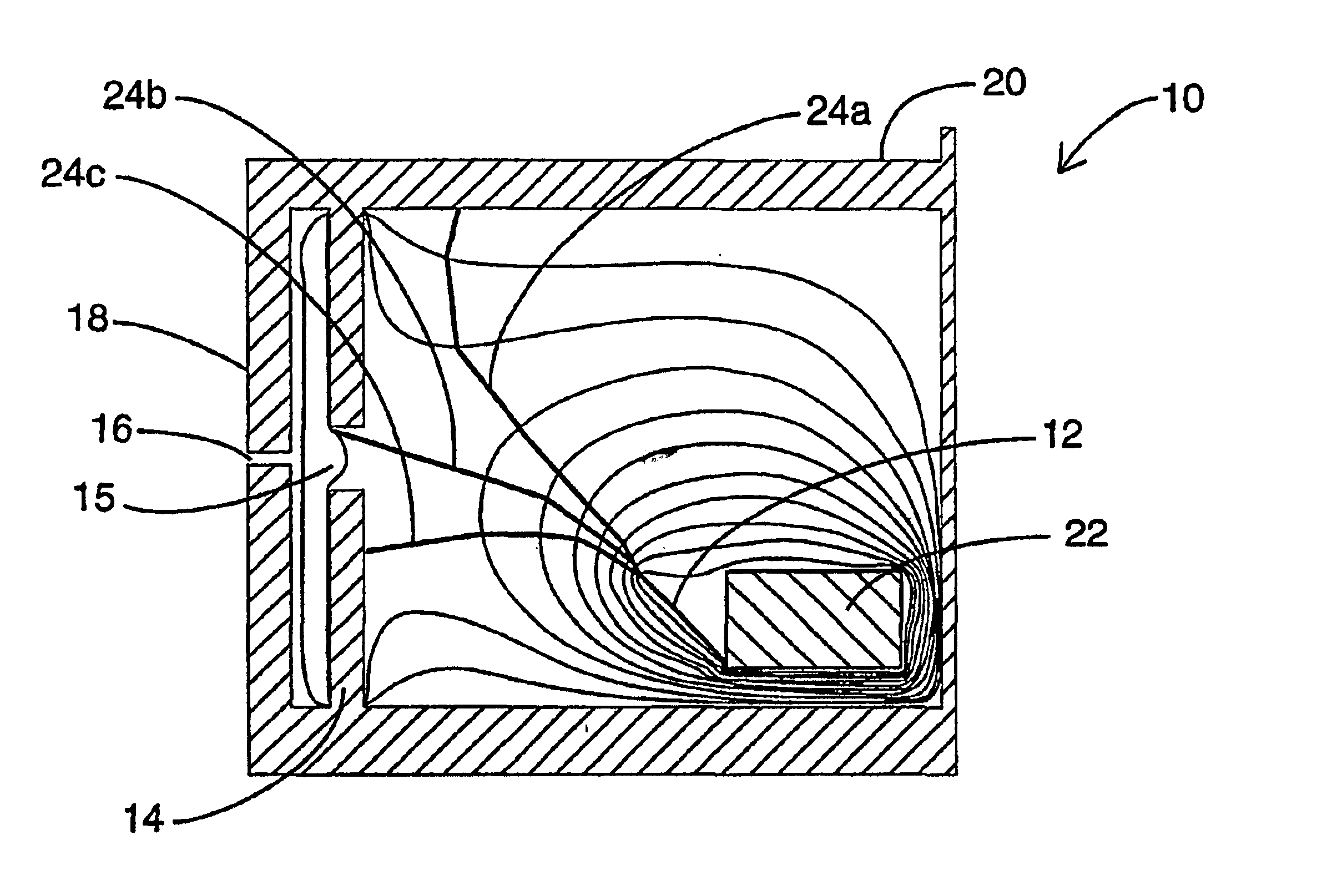
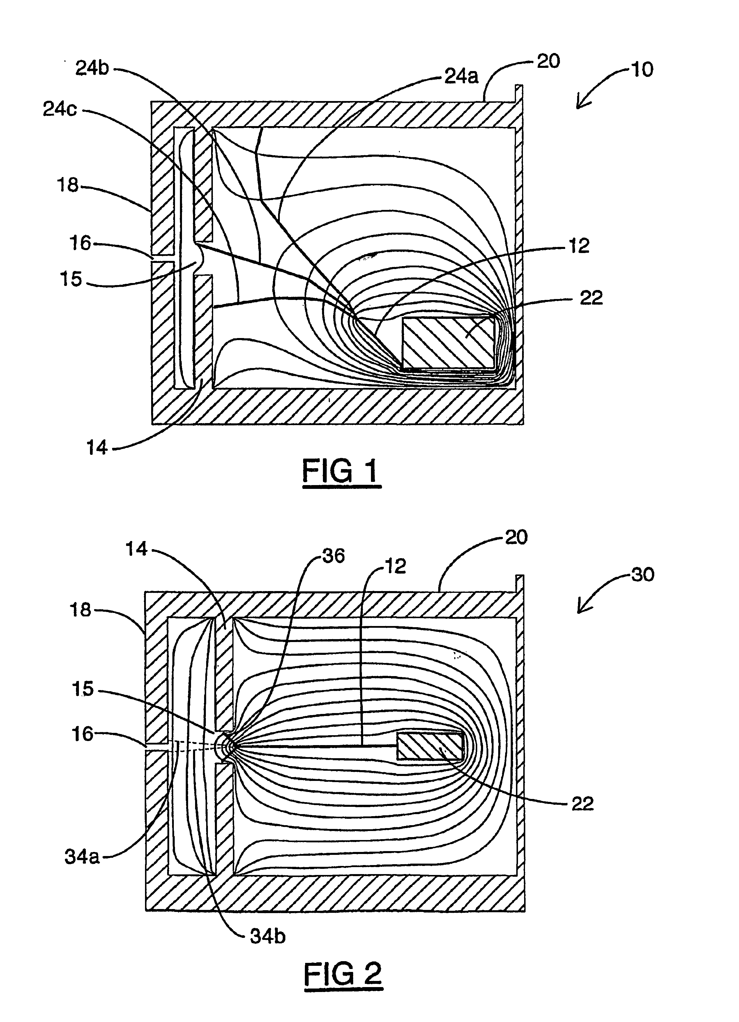
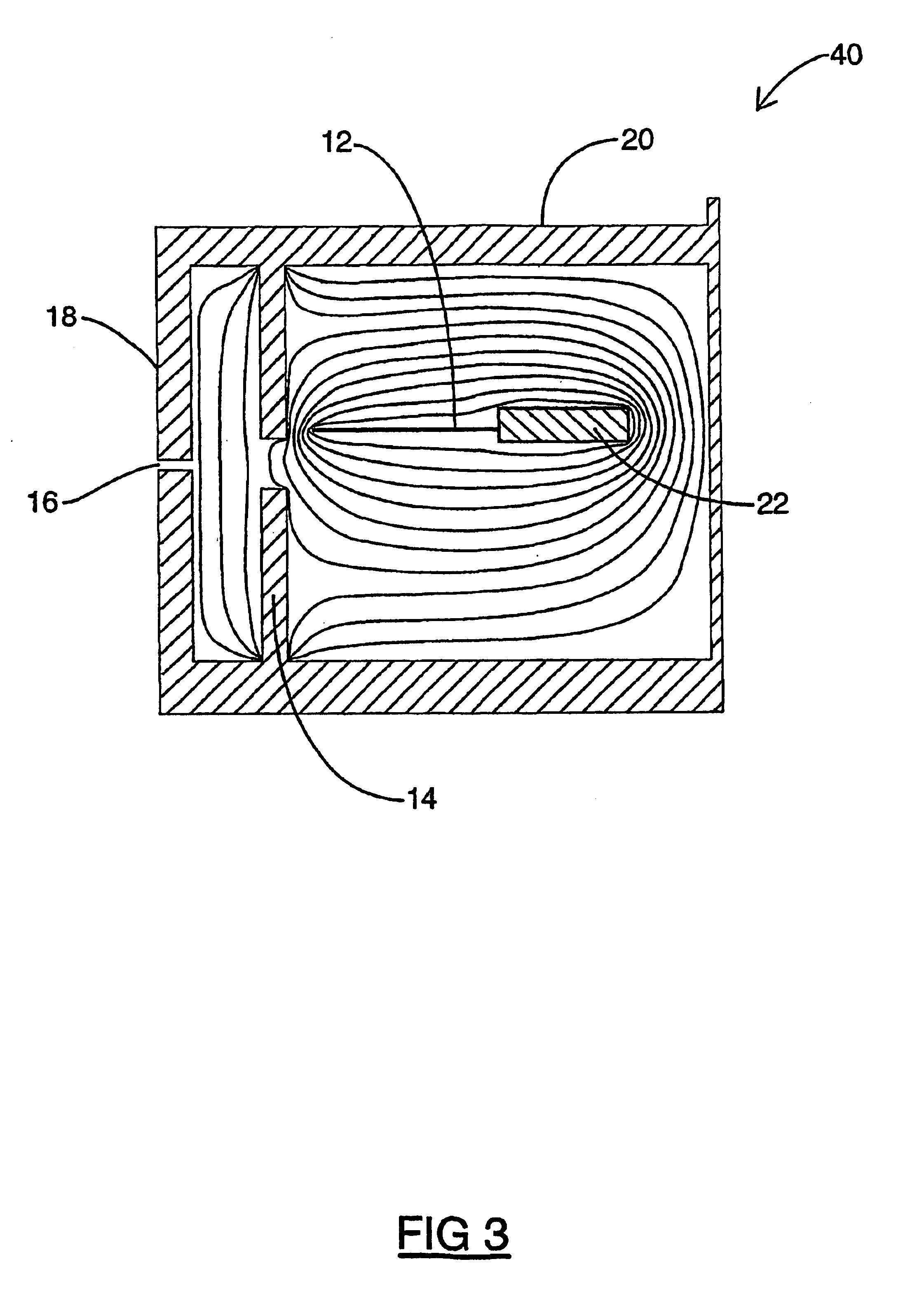
[0097]Simulation results for prior art ion source configurations will be described first. Referring to FIG. 1, a conventional ionspray or high flow-rate ESI ion source 10 is shown comprising a sprayer 12, a curtain plate 14, an aperture 15 in the curtain plate 14, an orifice 16 in an orifice plate 18, a housing 20 and a sprayer mount 22. The curtain plate 14, the orifice plate 18, and the housing 20 serve as counter electrodes for the ESI ion source 10. The region between the curtain plate 14 and the orifice plate 18 is at atmospheric pressure and is flushed with a gas such as nitrogen. The rest of the interior of the housing 20 is also at atmospheric pressure. The orifice plate 18 separates the atmospheric press...


PUM


Abstract

An ion lens is used to focus ions produced by various types of ion sources which are substantially at atmospheric pressure. The ions are focused to the inlet of a downstream mass spectrometer or other devices which require a larger and more stable ion flux improved performance. The ion lens is mounted in close proximity to the sprayer tip. The ion lens increases the total ion count rate summed over all of the generated ions. The ion lens may also be employed to vary the degree of ion fragmentation and the charge state pattern of the generated ions. The ion lens may also result in a more stable ion signal. Furthermore, more than one ion lens may be used. This invention may also be extended to multisprayer ion sources.

Description

REFERENCE TO RELATED APPLICATION[0001]This application is a national phase entry application of PCT application Ser. No. PCT / CA01 / 00728 filed on May 22, 2001. Accordingly, this application also claims priority from U.S. Provisional Patent Application Ser. No. 60 / 205,549 filed on May 22, 2000 and U.S. Provisional Patent Application Ser. No. 60 / 229,321 filed on Sep. 1, 2000.FIELD OF THE INVENTION[0002]The present invention relates to various types of ion sources such as, but not limited to, ionspray, electrospray, reduced liquid flow-rate electrospray, reduced liquid flow-rate ionspray, nanospray and atmospheric pressure chemical ionization (APCI) sources. More particularly, the present invention relates to increasing the ion signal stability and the ion flux generated by various types of electrospray ion sources.BACKGROUND OF THE INVENTION[0003]Electrospray ionization (ESI) is a method of generating ions in the gas phase at relatively high pressure. ESI was first proposed as a source...

Claims


Application Information

Patent Timeline
IPC IPC(8): B01D59/44H01J49/00G01N27/62H01J49/04H01J49/06H01J49/10
CPCH01J49/165H01J49/067
Inventor CHEN, DAVID D. Y.DOUGLAS, DONALD J.SCHNEIDER, BRADLEY B.
Owner THE UNIV OF BRITISH COLUMBIA
Learn More