
Image recording apparatus

Active Publication Date: 2019-08-01
BROTHER KOGYO KK
View PDF0 Cites 1 Cited by
  • Summary
  • Abstract
  • Description
  • Claims
  • Application Information

AI Technical Summary

Benefits of technology

The technical effect of this patent is to reduce or eliminate uneven concentrations (density) and white streaks caused by variations in the conveyance amounts of a recording medium during image recording without lengthening recording time. The invention achieves this by increasing the number of lines recorded in areas where two bands overlap with each other and reducing or eliminating the conveyance amount in the conveyance operation between certain recording passes. This results in a more consistent recording quality and a reduction in the number of bands required to record an image.

Problems solved by technology

in the above recording apparatus, when the number of lines to be recorded in an area where two bands overlap with each other is small, and when the conveyance amount of recording paper varies greatly, a white streak and unevenness in concentration may occur.
In that case, however, the number of bands required to record an image on recording paper increases, which may lengthen recording time.

Method used


Image

  • Image recording apparatus
  • Image recording apparatus
  • Image recording apparatus

Examples


first modified embodiment

[0083]In a first modified embodiment, the printer 1 can perform recording by selecting any of a high-speed recording mode (a second recording mode of the present disclosure) and a high-image-quality recording mode (a first recording mode of the present disclosure). The high-speed recording mode is selected when high speed is required, such as when text recording is performed. The high-image-quality mode is selected when a high image quality is required, such as when photo printing is performed. In order to shorten the time for conveyance operation, acceleration of the conveyance rollers 5 and 6 at the time of start of the conveyance operation and deceleration of the conveyance rollers 5 and 6 immediately before completion of the conveyance operation in the high-speed recording mode are greater than those in the high-image-quality recording mode.

[0084]In the first modified embodiment, as indicated in FIGS. 10A and 10B, when recording is performed by the high-speed recording mode (S20...

second modified embodiment

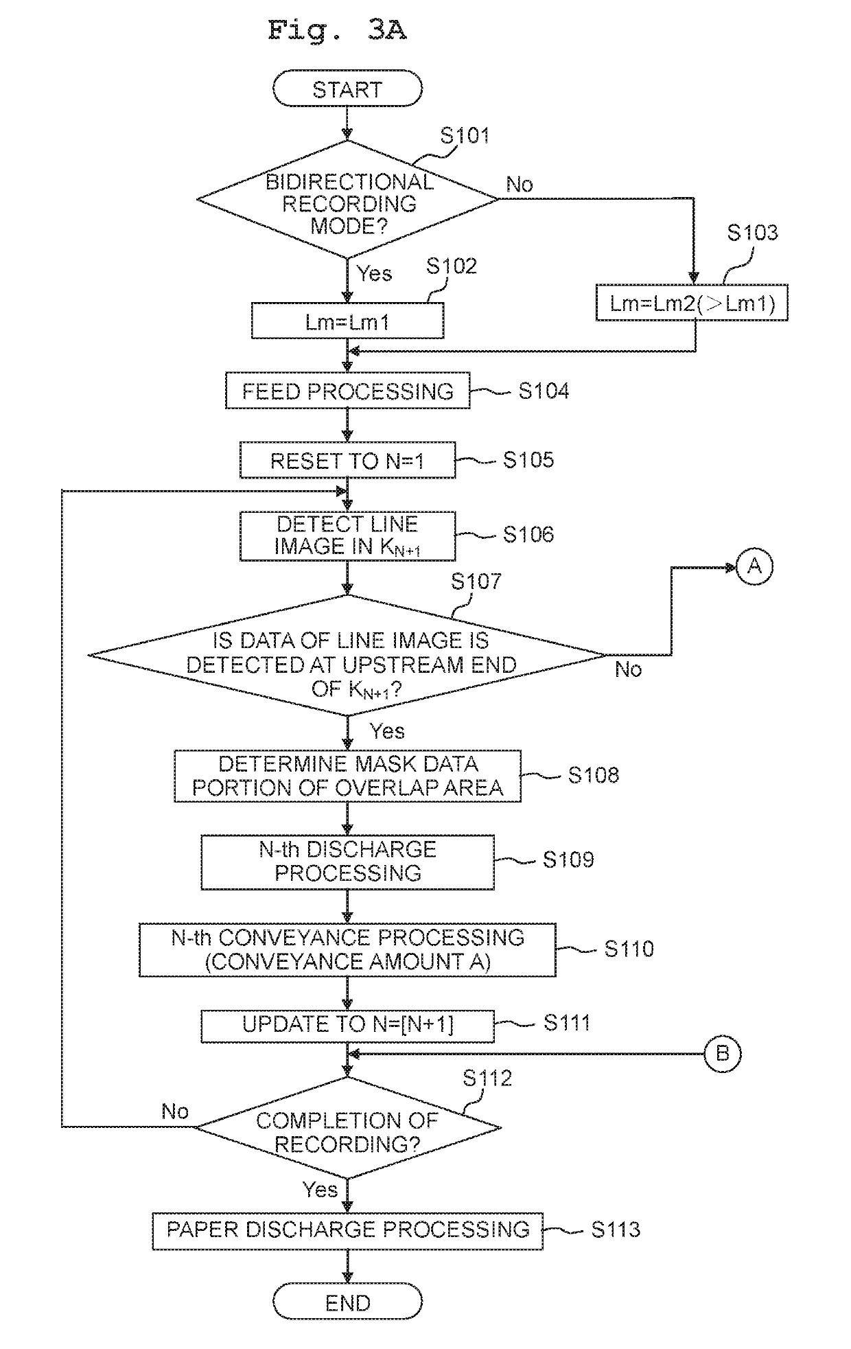
[0099]In the above embodiment, unlike the second modified embodiment, when the conveyance amounts of all the conveyance operations are set as the predefined conveyance amount A, and when the image data of the line image is not detected at the upstream end in the conveyance direction of the recording area KN+1, the image having the blank portion R as depicted in FIG. 6A is recorded.

[0100]In the second modified embodiment, when the image data of the line image T is not detected at the upstream end in the conveyance direction of the recording area KN+1, the conveyance amounts BN−1 and BN of the recording paper P in the [N−1]-th conveyance operation and the N-th conveyance operation are made to be smaller than the predefined conveyance amount A by [LrN+1 / 2]. Corresponding to this, allocation of the line image for each nozzle 10 is changed in each of the [N−1]-th recording pass, the N-th recording pass, and [N+1]-th recording pass. This lengthens the length in the conveyance direction of...


PUM


Abstract

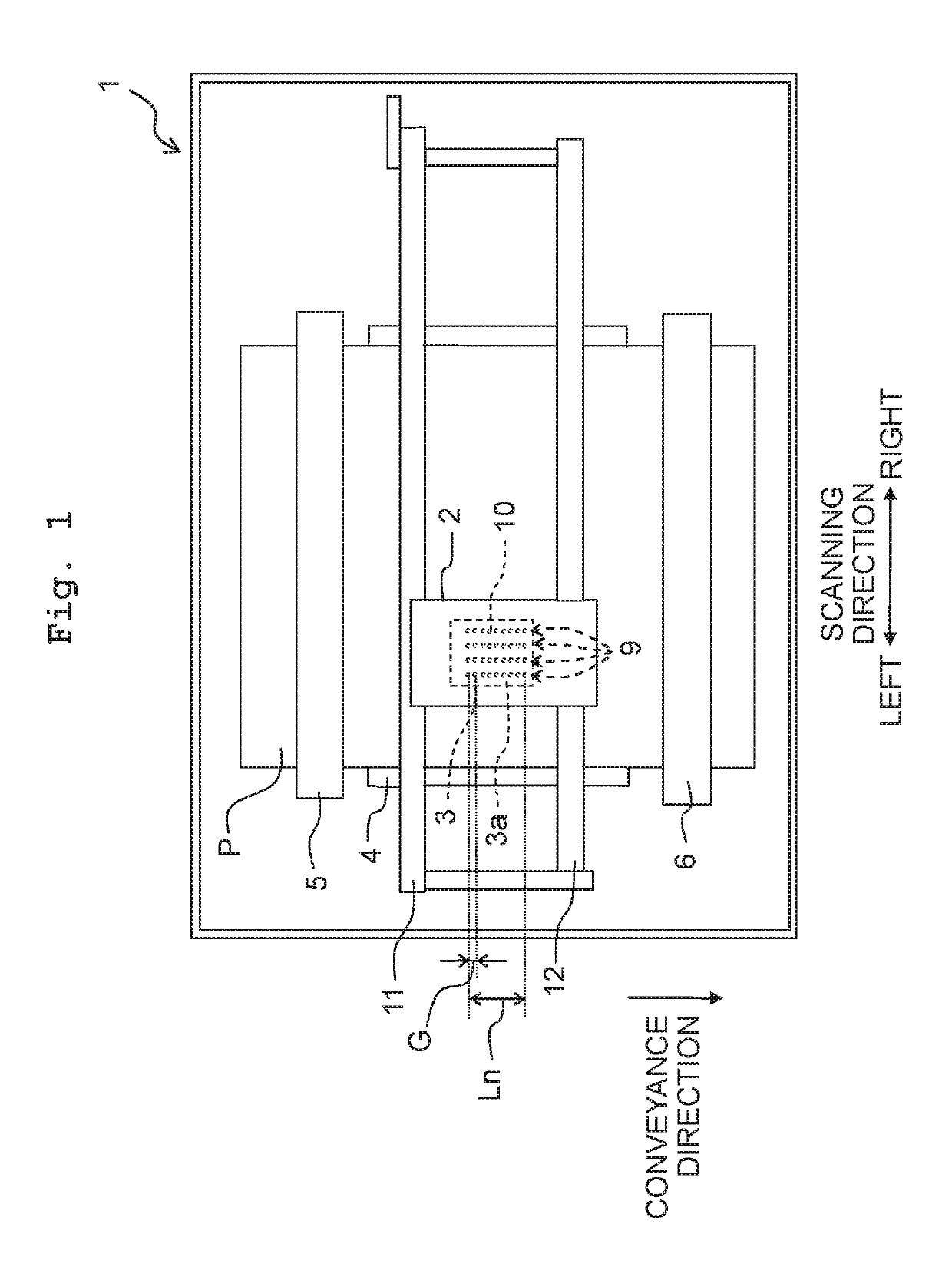
There is provided an image recording apparatus including: a conveyer, a carriage moving in a scanning direction, a recording head, and a controller. When the controller has not detected that image data of a line image corresponding to one line that extends in the scanning direction is present at an upstream end in a conveyance direction of the recording area for a next recording pass, the controller makes a conveyance amount of the recording medium in the conveyance operation between a certain recording pass and the next recording pass smaller than a case in which the controller has detected that the image data of the line image is present at the upstream end in the conveyance direction of the recording area for the next recording pass, by a predefined amount.

Description

CROSS REFERENCE TO RELATED APPLICATION[0001]The present application claims priority from Japanese Patent Application No. 2018-014424 filed on Jan. 31, 2018, the disclosure of which is incorporated herein by reference in its entirety.BACKGROUNDField of the Invention[0002]The present disclosure is related to an image recording apparatus configured to record an image on a recording medium.DESCRIPTION OF THE RELATED ART[0003]As an exemplary image recording apparatus that records an image, there is publicly known a recording apparatus that records an image by discharging ink from nozzles. The publicly known recording apparatus performs recording on recording paper by repeatedly and alternatingly performing recording of a band in which ink is discharged from nozzles during movement of a recording head in a scanning direction, and conveyance of recording paper in a sub-scanning direction. In the above recording apparatus, the recording paper is conveyed in the sub-scanning direction so tha...

Claims


Application Information

Patent Timeline
IPC IPC(8): B41J2/21B41J2/135
CPCB41J2/2132B41J2/135G06K15/107
Inventor ARAKANE, SATORU
Owner BROTHER KOGYO KK
Learn More