Convertible dental instrument

a technology of dental mirrors and convertible parts, applied in the field of dental mirrors, can solve the problems of high cost, high cost of special one-way mirrors, and high cost of mirror attachments in the '421 paten

Inactive Publication Date: 2006-06-27
COOPER IRA JEFFREY
View PDF22 Cites 14 Cited by
  • Summary
  • Abstract
  • Description
  • Claims
  • Application Information

AI Technical Summary

Benefits of technology

[0008]In order to overcome the disadvantages of the prior art and meet the objectives that have been outlined, the present invention provides an instrument system that is characterized by being convertible between two modes of illumination of the dental or oral cavity of a person. In one mode, a dental mirror with a light source self-contained in a hand piece is used with the illumination preferably being focused on the mirror so that the area being viewed is fully lighted. In the second mode of operation, a translucent rod is substituted to provide a light guide, so that other areas of the cavity can be illuminated by up close contact.
[0009]The hand piece has a handle section and an attachment section. A battery is mounted directly on the hand piece and a standard mirror with a metal stem and frame is attached to a first side of the attachment section. The light source is on a second side adjacent the mirror. A lens is mounted in a removable adapter and when aligned with the mirror focuses emitted light on to the mirror. When the mirror is removed from alignment with the light beam, then the system allows for direct illumination. In this manner within the broadest aspect of the present invention, the mirror / illuminator system provides full capability for illumination regardless of the mode of operation being used. The dentist, or other dental professional, can make an easy and quick transfer from one mode of viewing to another. Rather than removing the mirror from the hand piece, the user need only rotate the mirror away from the light beam path.
[0010]Preferably, the handle section and two sides of the attachment section together form the hand piece. The handle section is the base of the Y and reduced in size relative to the two sides, which in one of the preferred embodiments takes the form of arms of the Y. The battery is mounted on the proximate end of the handle section in such a manner to offset the weight of the arms and the selected attachments during use, such as the mirror and the light source. A connector extends through the hollow center of the hand piece. Due to the balance and the relatively slim profile of the hand piece, the mirror / illuminator of the present invention provides for enhanced ease of manipulation during use. The efficiency of use is thus increased over use of other prior devices, in addition to providing increased illuminating and viewing capability.
[0011]In accordance with another feature of the present invention, the light source chosen for the instrument system is a white light emitting diode [LED]. The LED provides superior illumination in the relatively small target area, but at the same time it is efficient in terms of having a low level of current draw, has a long life, is small and light weight and relatively low in initial cost.
[0013]In the second mode, a translucent plastic rod is used as the lens. The rod is mounted on an adapter that fits on the second arm in lieu of the basic lens that is used in conjunction with the mirror and for the relatively general illumination of the dental cavity. The rod provides the ability to get into close contact with the teeth and gums, such as for back lighting through individual teeth and in the gap between adjacent teeth. A lateral bend at the distal end of the rod facilitates the back lighting function and allows better, unobstructed viewing when used. The rod, like the mirror, can be rotated from side-to-side to provide the best positioning angle.
[0014]The housing and the battery at the proximate end of the hand piece counter balance the attachment section, the mirror and the light source. The micro switch that is mounted on the housing allows for easy access.

Problems solved by technology

The mirror attachment in the '421 patent is also relatively expensive in that a special light transmitting plastic mirror frame and stem is required.
Again, this invention is characterized by relatively high cost due to the special molded mirror frame; but in addition, the cost of the special one-way mirror is particularly high.

Method used


Image

  • Convertible dental instrument
  • Convertible dental instrument

Examples


Embodiment Construction

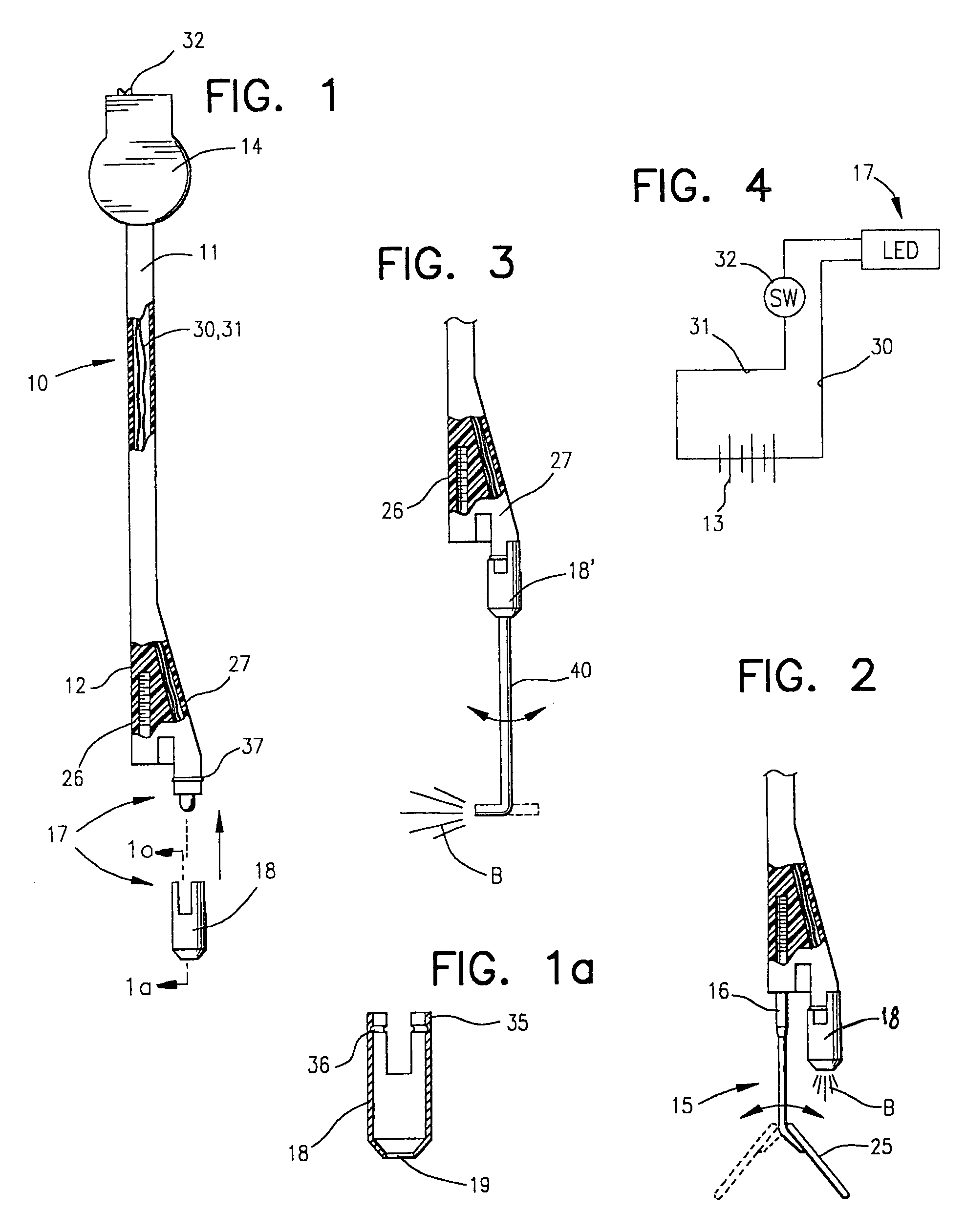
[0023]Considering FIGS. 1, 1a and 2 of the present invention for a more detailed understanding of the specifics of the preferred embodiment, a dental hand piece 10 is shown in conjunction with the basic concept of a first mode of operation with a standard dental mirror and to broadly illuminate the dental or oral cavity of a person. The hand piece 10 has a handle section 11 and an attachment section 12. A battery 13 [see FIG. 4] is in a housing 14 on the hand piece 10. A removable mirror assembly, generally designated by the reference numeral 15, is attached by a threaded stem 16 on a first side of the attachment section 12. A light source, generally designated with the numeral 17 is on the second side of the attachment section 12. A basic adapter 18 [see enlarged view in FIG. 1a] has a lens 19 that serves to properly focus the emitted light from the light source 17. This basic combination mirror / illuminator is capable of efficiently illuminating the dental cavity in two distinct mo...


PUM


Abstract

A self-contained and convertible dental instrument system includes both a lighted mirror and a direct illuminator. A hand piece has a handle section, including a battery in a housing, and a dual attachment section to receive a mirror and a light source. The illumination can be by reflection by said mirror or directly upon removal of the mirror from alignment with the light source. The handle and attachment sections preferably form a Y with the handle section reduced in size for balance and enhanced manipulation. The light source is an LED, is connected through wires in the hand piece to the battery and is controlled by a switch on the battery housing. A lens for the LED is attached by a snap-on adapter. For close contact illumination in the dental cavity, the lens includes a translucent rod, also attached by an adapter. The mirror and rod are rotatable for angular positioning to improve the illumination and the viewing.

Description

[0001]This is a continuation application of U.S. patent application Ser. No. 10 / 216,144, filed Aug. 9, 2002 now abandoned, entitled “Convertible Dental Instrument.”BACKGROUND OF THE INVENTION[0002]The present invention relates to dental instruments, and more particularly, to illuminated dental mirrors and related direct illuminators for the dental cavity to provide the required light for a dentist to efficiently perform work on a patient's mouth.[0003]A dental mirror is historically the universal tool for good dentistry. It allows the dentist to see in hard to reach places in the dental or oral cavity, such as behind the teeth. This viewing is essential to a good inspection of the teeth and gums of a patient. Without it, early cavities or gum disease could be missed during a regular visit. Improvements have been made in illumination over the years, such as providing better overhead lights, but increasing illumination in the cavity is the key for even better viewing. The illumination...

Claims


Application Information

Patent Timeline
IPC IPC(8): A61C1/00
CPCA61B1/0684A61B1/247A61C1/088
Inventor COOPER, IRA JEFFREY
Owner COOPER IRA JEFFREY
Why Eureka
Try Eureka