Nitride compound semiconductor light emitting device and method for producing the same
a light-emitting device and compound semiconductor technology, which is applied in semiconductor devices, lasers, semiconductor lasers, etc., can solve the problems of high emission intensity, high defect concentration, and high nitrogen vacancy of nitride compound semiconductor crystals formed on conventional sapphire substrates, and achieve low operation voltage
- Summary
- Abstract
- Description
- Claims
- Application Information
AI Technical Summary
Benefits of technology
Problems solved by technology
Method used
Image
Examples
example 1
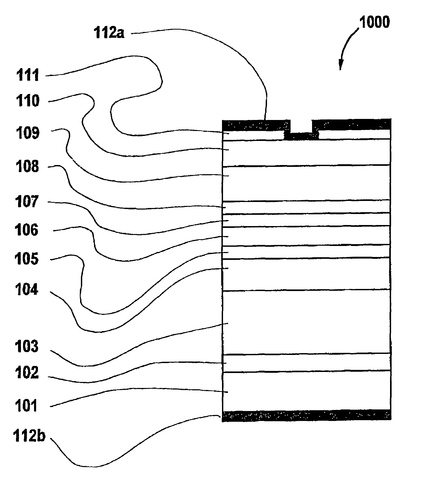
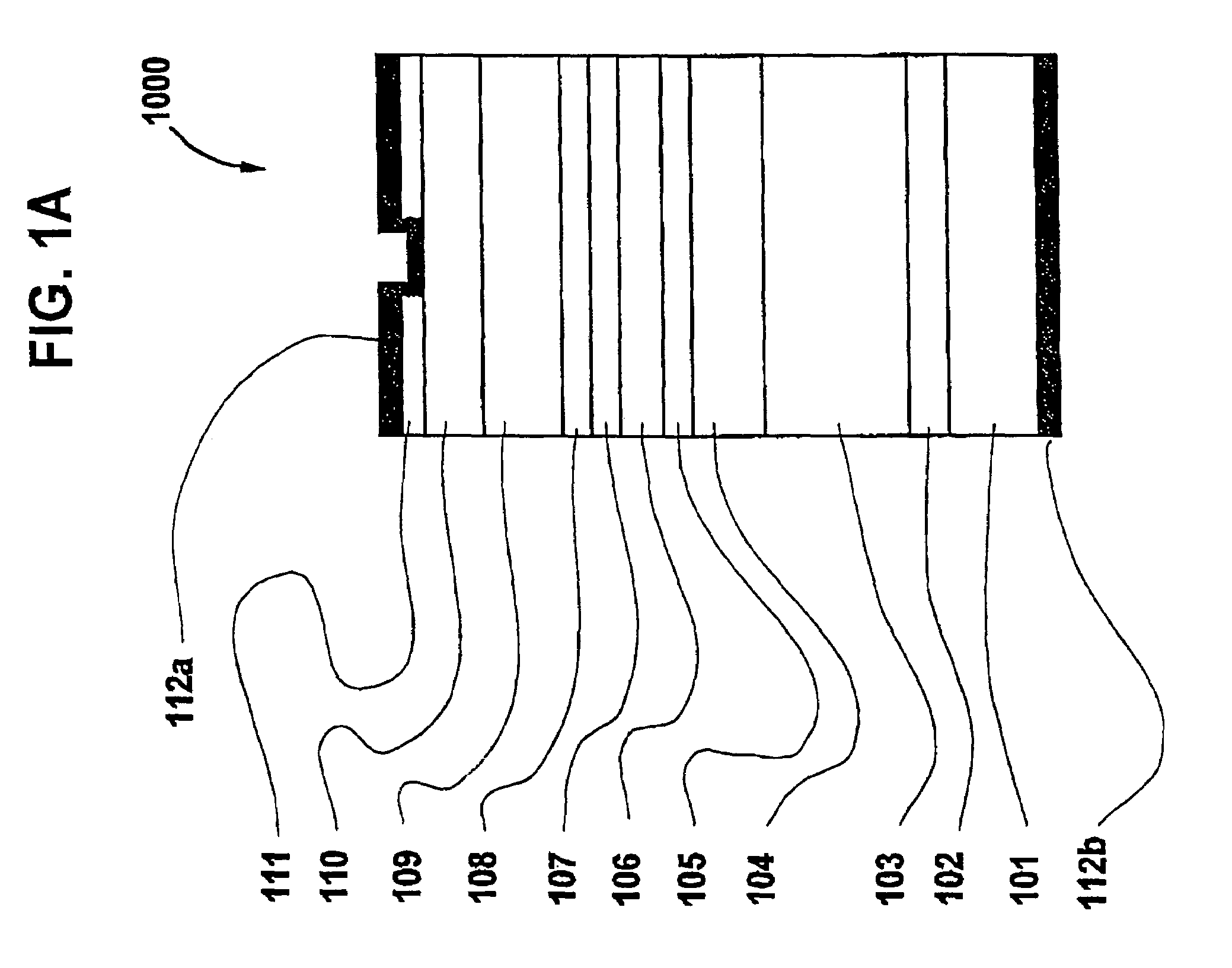
[0049]FIG. 1A is a schematic cross-sectional view illustrating a light emitting device 1000 according to the present invention. First, a GaN substrate 101 whose crystal orientation is tilted away from the direction by an angle in the range from about 0.05° to about 2° in the or direction is prepared. In the present specification, a substrate as defined above will be referred to as a “slightly-tilted substrate”.
[0050]Upon the slightly-tilted GaN substrate 101, a GN buffer layer 102, an n-GaN layer 103, an n-AlGaN light confining layer 104 for confining light emitted from an active layer, and a GaN lower optical guide layer 105 are laminated in this order to a total thickness of about 1 μm or more. The GaN buffer layer 102 is optional and can be omitted. The lower optical guide layer 105 may be doped so as to have n-type properties. Further layers that may generally be used for a light emitting device, e.g., a crack prevention layer and / or a carrier barrier layer, may be added to t...
example 2
[0073]In Example 2 of the present invention, a semiconductor light emitting device 1000 in the form of an LED is produced, using a slightly-tilted substrate 101. In the present example, the relationship between a tilting angle of a slightly-tilted substrate and density of threading dislocations present in the semiconductor light emitting device 1000, surface roughness, and emission intensity with current injection will be discussed.
[0074]By using a GaN substrate 101 having a mirror-polished (0001) plane whose crystal orientation is actually tilted away from the direction by a slight angle in the range from about 0.02° to about 5° in the or direction, a nitride compound semiconductor multilayer structure is grown in the manner shown in Example 1.
[0075]After an n-GaN layer 103 is formed, growth conditions for the active layer 106 are adjusted so that a constant substrate temperature is maintained while supplying NH3. Once a stable substrate temperature is achieved, TMG, TMI, and Si...
example 3
[0081]A semiconductor light emitting device 1000 was produced by a method similar to Example 2 while varying the thickness of the n-GaN layer 103, except that the growth temperature for the active layer 106 was fixed at about 750° C. FIG. 10 shows results of a surface roughness plotting for the semiconductor light emitting device 1000 according to the present example with respect to the total thickness of the underlying layers between the substrate 101 and the active layer 106.
[0082]In FIG. 10, “●” plots represent results obtained with a substrate tilt angle of 0.15° in the direction from; “◯” plots represent results obtained with a substrate tilt angle of 5° in the direction; “♦” plots represent results obtained with a substrate tilt angle of 1.7° in the direction; and “⋄” plots represent results obtained with a substrate tilt angle of 0.04° in the direction. From FIG. 10, it can be seen that, irrespective of the crystal orientation, the flatness of the uppermost surface of the...
PUM
 Abstract
Description
Claims
Application Information
 - R&D
- Intellectual Property
- Life Sciences
- Materials
- Tech Scout
- Unparalleled Data Quality
- Higher Quality Content
- 60% Fewer Hallucinations
Browse by: Latest US Patents, China's latest patents, Technical Efficacy Thesaurus, Application Domain, Technology Topic, Popular Technical Reports.
© 2025 PatSnap. All rights reserved.Legal|Privacy policy|Modern Slavery Act Transparency Statement|Sitemap|About US| Contact US: help@patsnap.com


