Intra-cavity etalon with asymmetric power transfer function

a technology of asymmetric power transfer and etalon, applied in the field of lasers, can solve the problems of small channel separation, impede stable, single mode lasing, and complicating the servo function associated with laser operation

Inactive Publication Date: 2006-06-13
INTEL CORP
View PDF15 Cites 10 Cited by
  • Summary
  • Abstract
  • Description
  • Claims
  • Application Information

AI Technical Summary

Problems solved by technology

Greater bandwidth requirements will likely result in smaller channel separation in the future.
One drawback common to many external cavity lasers with intra-cavity etalons is an asymmetric mode pulling effect during laser operation that hinders stable, single mode lasing and complicates servo functions associated with laser operation.

Method used


Image

  • Intra-cavity etalon with asymmetric power transfer function
  • Intra-cavity etalon with asymmetric power transfer function
  • Intra-cavity etalon with asymmetric power transfer function

Examples


Embodiment Construction

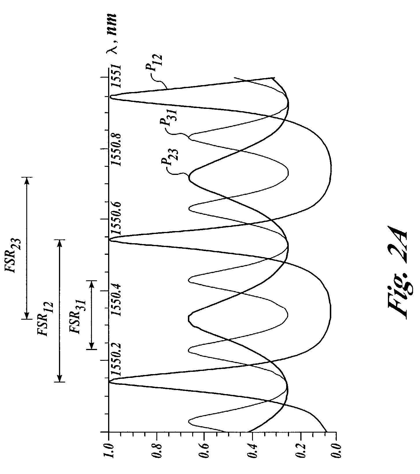
[0013]Aspects of various embodiments of the present invention provide apparatus and methods for compensation of asymmetric mode pulling in external cavity lasers. In one aspect, a wavelength locker or etalon device is configured to provide an asymmetric power transfer function and generate a transmission peak or peaks of asymmetric shape. The asymmetry of the transmission peak may be in the form of a steeper slope on the long wavelength side of the peak than on the short wavelength side. The asymmetry of the transmission peak or peaks may be structured and configured to compensate or correct for asymmetric mode pulling effects that arise in external cavity lasers during single mode laser operation.

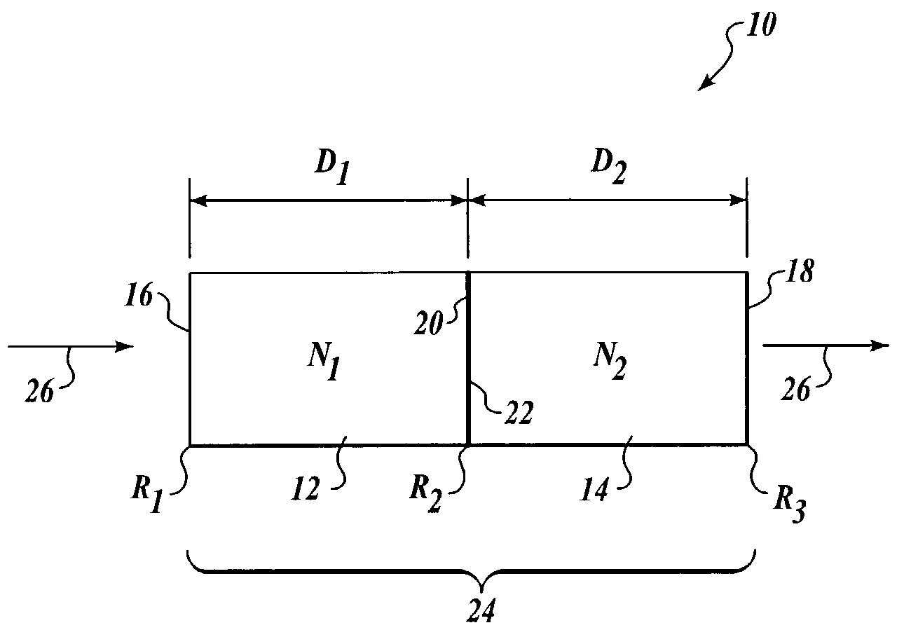
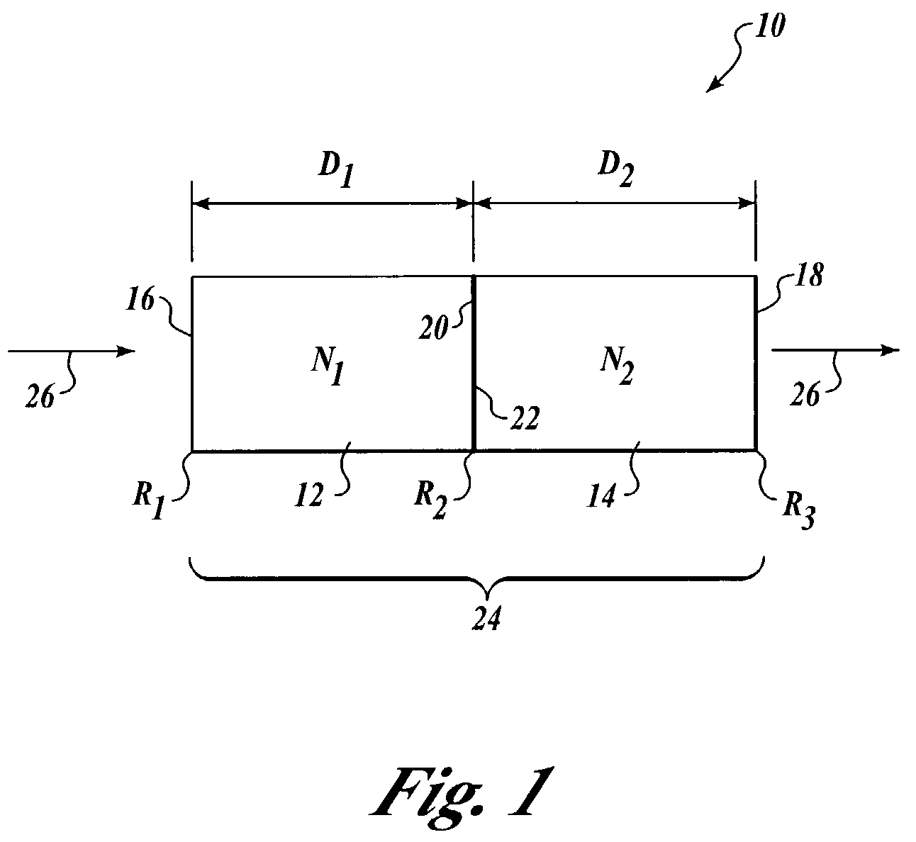
[0014]Another aspect of the present invention may have at least two pairs of mutually parallel reflective surfaces configured to define the asymmetric power transfer function. For example, the two pairs of reflective surfaces can be implemented with two etalons. In certain embodiments, the...


PUM


Abstract

Apparatus and methods for compensation of asymmetric mode pulling in external cavity lasers and the like. An apparatus includes a wavelength locker or etalon device to provide an asymmetric power transfer function and generate a transmission peak or peaks of asymmetric shape. The asymmetry of the transmission peak may be in the form of a steeper slope on the long wavelength side of the peak than on the short wavelength side. The asymmetry of the transmission peak or peaks may be structured to compensate or correct for asymmetric mode pulling effects that arise in laser gain media during single mode laser operation.

Description

FIELD OF THE INVENTION[0001]The present invention relates to optical communications systems and, more particularly, to lasers used in optical communication systems. Still more particularly, the present invention is related to etalon devices used in implementing such lasers.BACKGROUND INFORMATION[0002]The demand for increased bandwidth in fiber optic telecommunications has driven the development of sophisticated transmitter lasers usable for dense wavelength division multiplexing (DWDM) systems wherein multiple separate data streams propagate concurrently in a single optical fiber. Each data stream is created by the modulated output of a semiconductor laser at a specific channel frequency or wavelength, and the multiple modulated outputs are combined onto the single fiber. The International Telecommunications Union (ITU) presently requires channel separations of 50 GHz, or approximately 0.4 nanometers, which allows up to 128 channels to be carried by a single fiber within the bandwid...

Claims


Application Information

Patent Timeline
Patent Type & Authority Patents(United States)
IPC IPC(8): H01S3/10G02B6/34H01S3/098
CPCH01S3/08036G02B6/2931G02B6/29358
Inventor SOCHAVA, SERGEI L.CHAPMAN, WILLIAM B.
Owner INTEL CORP
Why Eureka
Try Eureka