Method of supplying divided gas to a chamber from a gas supply apparatus equipped with a flow-rate control system

a flow-rate control system and gas supply method technology, applied in the direction of liquid handling, instruments, packaged goods types, etc., can solve the problems of inability to control the flow rate, limited practical range of flow rate control, and increase the cost of facilities, so as to achieve the effect of low flow rate control accuracy, easy operation and maintenance, and easy operation

Inactive Publication Date: 2006-06-13
FUJIKIN INC +1
View PDF6 Cites 21 Cited by
  • Summary
  • Abstract
  • Description
  • Claims
  • Application Information

AI Technical Summary

Benefits of technology

[0019]It is an object of the present invention to provide a method of supplying divided gas to a chamber from a gas supply apparatus equipped with a pressure-type flow-rate control system which solves the above-mentioned problems that are encountered when a gas G at a given flow rate Q, adjusted by the pressure-type flow-rate control system FCS, is divided into split supply lines GL1 and GL2 with set flow-rates Q1 and Q2 according to a conventional method of dividing a gas supply from a gas supply apparatus equipped with a pressure-type flow-rate control system FCS to a chamber C, namely: ① the flow rate Q controlled by the pressure-type flow-rate control system FCS may deviate greatly from the set flow rate with the result that it is extremely difficult to adjust not only the flow rate Q, but also the flow rates Q1 and Q2, if the control method adopted is one in which flow rate control valves V1 and V2 installed in the split supply lines GL1 and GL2 are first closed completely (or almost closed) and then opened gradually; and ② the precision of the flow rate control is low and / or it takes too much time to control the flow rate, even if the flow rates Q1 and Q2 are somehow adjusted. It is, therefore, another object of the present invention to provide a method of supplying divided gas to a chamber from a gas supply apparatus equipped with a pressure-type flow-rate control system in which gas at a predetermined flow rate Q can be quickly divided and supplied at a desired ratio Q1 / Q2 with great precision, even if the gas is divided and supplied from a gas supply apparatus equipped with a pressure-type flow-rate control system FCS.DISCLOSURE OF THE INVENTION
[0020]To achieve the above stated object, the inventors of the present invention have rejected the conventional method used in divided gas supply control for this type of gas supply apparatus in which respective flow-rate control valves V1 and V2 installed in split lines are gradually opened from being completely closed (or almost completely closed), and have instead adopted a novel method in which the flow-rate control valves V1 and V2 are closed stepwise from being initially fully open (or almost fully open), so that the flow rates Q1 and Q2 of the split supply lines GL1 and GL2 can be adjusted to a desired flow rate ratio Q1 / Q2 quickly and with precision, while the overall flow rate Q is controlled with precision by means of the pressure-type flow-rate control system FCS. The inventors have conducted many experiments on the supply of divided gas on the basis of the above-mentioned novel method.

Problems solved by technology

Hence, it is a disadvantage of the pressure-type flow-rate control apparatus FCS that when the gas pressure P2 on the downstream side of the orifice rises greatly and disproportionately compared with the gas pressure P1 on the upstream side of the orifice, the critical expansion pressure condition is no longer satisfied, making it impossible to control the flow rate.
As a result, there is a problem in that the practical range for flow rate control is limited when the pressure P2 on the downstream side of the orifice increases.
As described above, it is noted that numerous problems arise in connection with gas flow rate control using a pressure-type flow-rate control system when the pressure P2 on the downstream side of the orifice L increases.
However, it is not recommended that gas be supplied to a single chamber C using gas supply lines GL1 and GL2 having independent pressure-type flow-rate control systems FCS1 and FCS2 respectively, because the semiconductor manufacturing equipment is then forced to be enlarged, the facility cost increases, and maintenance becomes laborious.
Therefore, with the aforementioned pressure-type flow-rate control system FCS, when the pressure P2 downstream of the orifice exceeds approximately 100 Torr, the range of flow rate control is greatly limited with respect to the precision of flow rate control.

Method used


Image

  • Method of supplying divided gas to a chamber from a gas supply apparatus equipped with a flow-rate control system
  • Method of supplying divided gas to a chamber from a gas supply apparatus equipped with a flow-rate control system
  • Method of supplying divided gas to a chamber from a gas supply apparatus equipped with a flow-rate control system

Examples


Embodiment Construction

[0083]The following embodiment of the present invention is described with reference to the attached drawings hereunder.

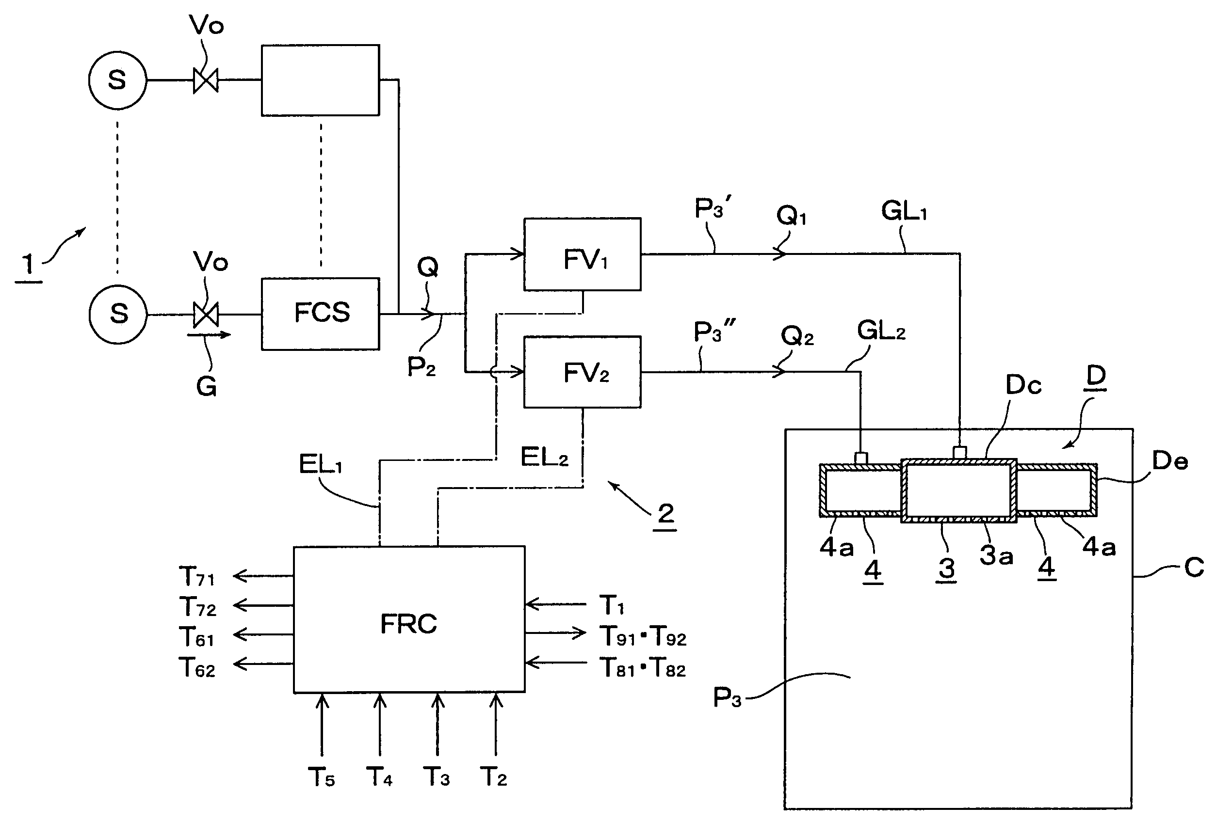
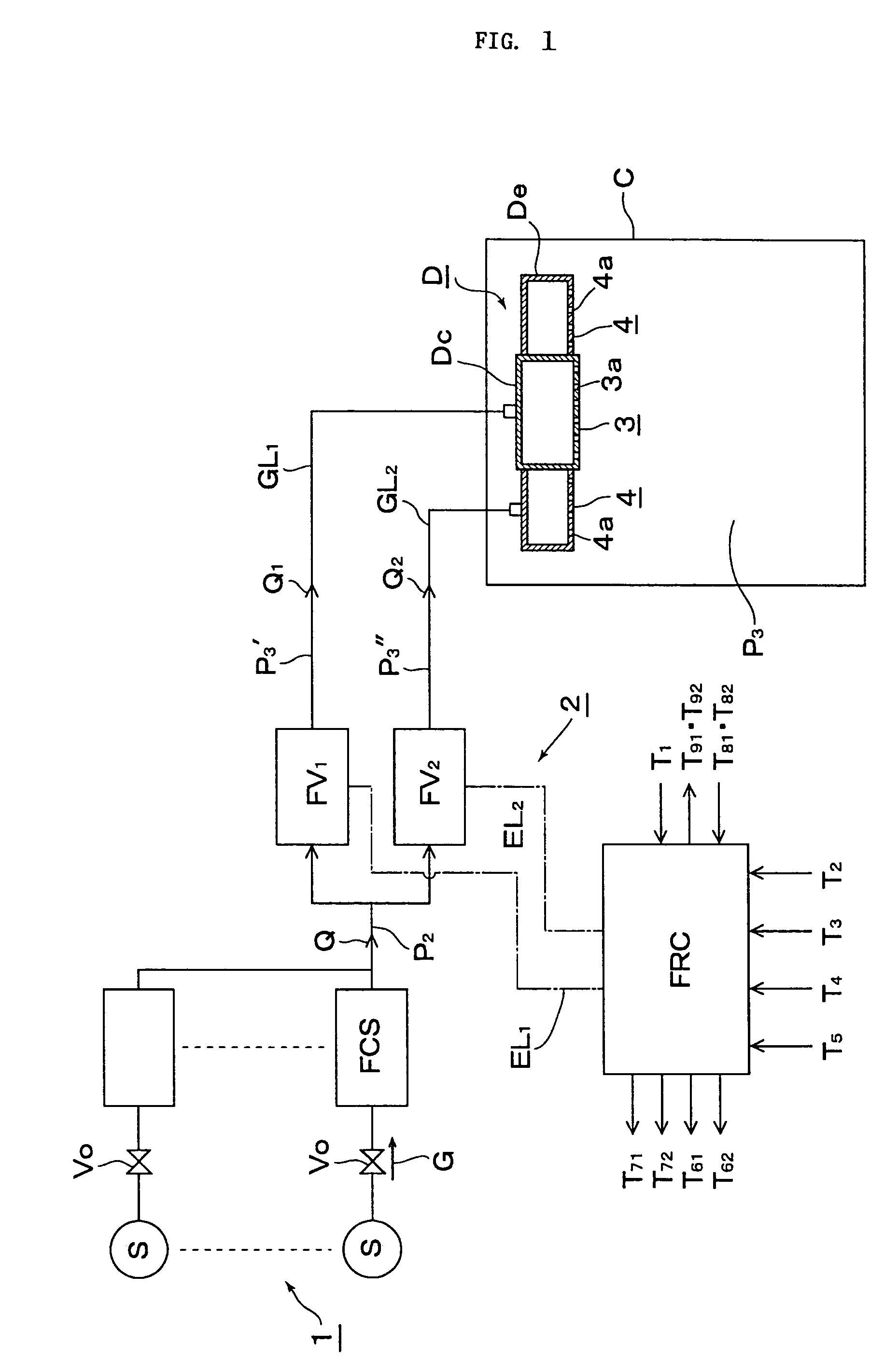
[0084]FIG. 1 is a complete diagrammatic view illustrating a method of supplying a divided gas to a chamber from a gas supply apparatus equipped with a flow-rate control system according to the present invention.

[0085]Referring to FIG. 1, a gas supply apparatus 1 comprises inter alia a supply source S of a treatment gas G, a gas main valve Vo, and a pressure-type flow-rate control system FCS.

[0086]A divided flow-rate control system 2 comprises inter alia split pressure-type flow-rate controllers FV1 and FV2, and a divided flow-rate control board FRC. Furthermore, referring to FIG. 1, C designates a chamber, D a gas discharger, Dc a centre part gas discharger, De an edge part gas discharger, GL1 a centre part split supply line, GL2 an edge part split supply line, Q the total gas flow rate, Q1 and Q2 the divided flow rates, P2 the pressure on the downstream side of the...


PUM

PropertyMeasurementUnit
pressureaaaaaaaaaa
pressureaaaaaaaaaa
outer diameteraaaaaaaaaa

Abstract

A method for supplying a specified quantity Q of processing gas while dividing at a desired flow rate ratio Q1 / Q2 accurately and quickly from a gas supply facility equipped with a flow controller into a chamber. When a specified quantity Q of gas is supplied while being divided at a desired flow rate ratio Q1 / Q2 from a gas supply facility equipped with a flow controller into a reduced pressure chamber C through a plurality of branch supply lines and shower plates fixed to the ends thereof, pressure type division quantity controllers FV1 and FV2 are provided in the plurality of branch supply lines GL1 and GL2. Opening control of both division quantity controllers FV1 and FV2 is started by an initial flow rate set signal from a division quantity control board FRC for fully opening the control valve CV of the pressure type division quantity controller having a higher flow rate and pressures P3′ and P3″ on the downstream side of the control valve CV are regulated thus supplying a total quantity Q=Q1+Q2 of gas while dividing into the chamber C through orifice holes (3a, 4a) made in shower plates (3, 4) at desired division quantities Q1 and Q2 represented by formulas Q1=C1P3′ and Q2=C2P3″ (where, C1 and C2 are constants dependent on the cross-sectional area of the orifice hole or the gas temperature on the upstream side thereof).

Description

[0001]This is a National Phase Application in the United States of International Patent Application No. PCT / JP03 / 100437 filed Jan. 20, 2003, which claims priority on Japanese Patent Application No. 2002-161086, filed Jun. 3, 2002. The entire disclosures of the above patent applications are hereby incorporated by reference.FIELD OF THE INVENTION[0002]The present invention relates to an improved method of gas supply for supplying automatically divided gas to a chamber from a gas supply apparatus equipped with a pressure-type flow-rate control system for use in semiconductor manufacturing at semiconductor manufacturing facilities and the like.BACKGROUND OF THE INVENTION[0003]The so-called “pressure-type” flow-rate control system has been widely employed for the purpose of controlling the flow rate of gas to be supplied to semiconductor manufacturing facilities.[0004]FIG. 7 illustrates an example of a situation where a treatment gas G is supplied to a chamber C for forming silicone diox...

Claims


Application Information

Patent Timeline
Patent Type & Authority Patents(United States)
IPC IPC(8): B65B1/04G05D7/06H01L21/205
CPCG05D7/0664Y10T137/7761Y10T137/7759G05D7/06
Inventor SUGIYAMA, KAZUHIKOIKEDA, NOBUKAZUNISHINO, KOUJIDOHI, RYOSUKEUENOYAMA, TOYOMI
Owner FUJIKIN INC
Why Eureka
Try Eureka