
Refrigerating capacity control device, a testing apparatus and a refrigerating control method using the device

a technology of refrigerating capacity and control device, which is applied in the direction of cooling fluid circulation, domestic cooling apparatus, lighting and heating apparatus, etc., can solve the problems of difficult application of this technology in general purpose appliances and equipment, difficulty in optimizing refrigerating capacity and precise temperature control of electronic expansion valve as throttling device, etc., and achieves the effect of low control precision

Inactive Publication Date: 2015-04-23
XUTEMP TEMPTECH
View PDF20 Cites 2 Cited by
  • Summary
  • Abstract
  • Description
  • Claims
  • Application Information

AI Technical Summary

Benefits of technology

This patent describes a refrigerating device that uses a hot-gas valve to control the refrigerant output, allowing for precise control of refrigerating capacity and temperature between -30°C and +30°C. The device also includes a pressure regulatory valve to control the refrigerant entering the condenser, ensuring continuous operation and eliminating the need for a traditional thermal expansion valve. The invention overcomes the limitations of traditional valves and ensures accurate and efficient operation in extreme temperatures.

Problems solved by technology

For the requirements of accurate temperature control and the features of small quantity and diversities for application, the refrigerating capacity and energy saving control of climatic and environmental testing equipment have been an important subject but are neglected for long times. The temperature control for almost all climatic and environmental testing equipment incorporating refrigerating device are based on conventional technology of continuous refrigeration and additional counter heating, resulting in increased electric current drawing and substantial energy waste.
Without extensive marketing survey, sufficient budget for engineering and manufacturing investment, it is difficult to apply this technology in general purpose appliance and equipment.
Because of the specific purpose of superheat control, the electronic expansion valve as throttling device has the limitation for optimized refrigerating capacity and precise temperature control.
Therefore, the degree of complexity and reliability for the control circuit and software algorithm becomes critical to the success of the system.
Without optimistic prospect of industrialization and sufficient budget for engineering and manufacturing investment for mass production, it is difficult to afford the expensive cost for a sophisticated and reliable system.
In the mean time, the application temperature range of traditional electronic expansion valve is limited between ambient temperature and −40° C., while the requirements for application in climatic and environmental testing equipment are extended down to −90° C. and up to +300° C. With the status of small quantity and diversity in application, it is difficult to apply the electronic expansion valve in climatic and environmental testing equipment for precise temperature and refrigerating capacity control, in the traditional way as in household and commercial appliances.
As a result, the refrigerating capacity is restrained, the cooling is limited and even heating is possible.
(1) Due to the restrain from the service life of a solenoid valve, the operation interval of the hot gas bypassing should be limited to certain extent. As a result, the control precision of refrigerating capacity is also limited;
(2) With the solenoid valve remaining opened for a long time under continuous heating condition, the discharge pressure of the compressor will decrease gradually. As a result, the refrigerating device based on hot-gas bypassing can only achieve limited heating or even no heating. It is actually difficult to maintain an operating temperature close to or higher than ambient;
(3) With the function and operation of a solenoid valve, it emits unfavorable noise including that of valve operation and that of hot-gas flow; and
(4) The stress of pressure impact resulting from operating of the solenoid valve creates additional fatigue and reduces the service life of related refrigerating parts or components, including the solenoid valve itself.

Method used


Image

  • Refrigerating capacity control device, a testing apparatus and a refrigerating control method using the device
  • Refrigerating capacity control device, a testing apparatus and a refrigerating control method using the device
  • Refrigerating capacity control device, a testing apparatus and a refrigerating control method using the device

Examples


Embodiment Construction

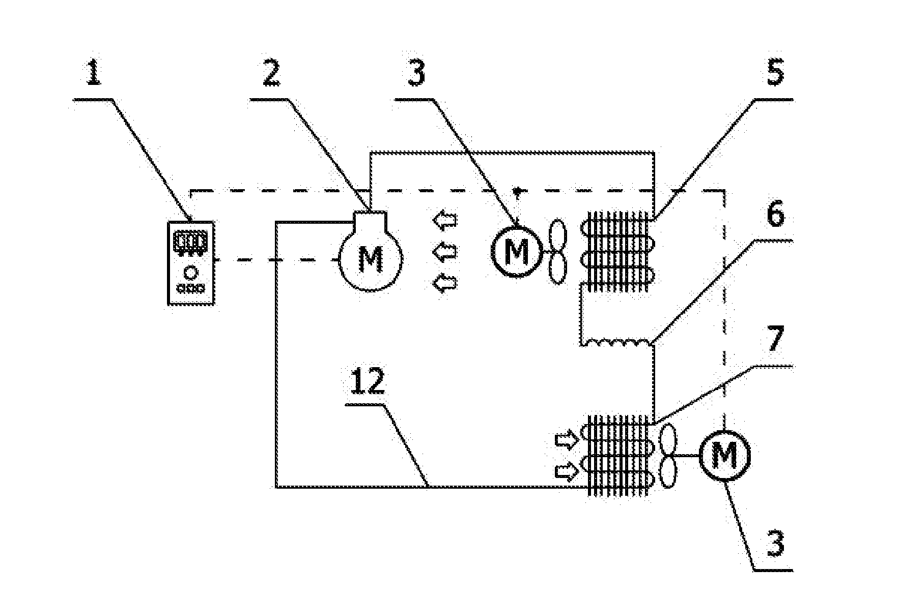
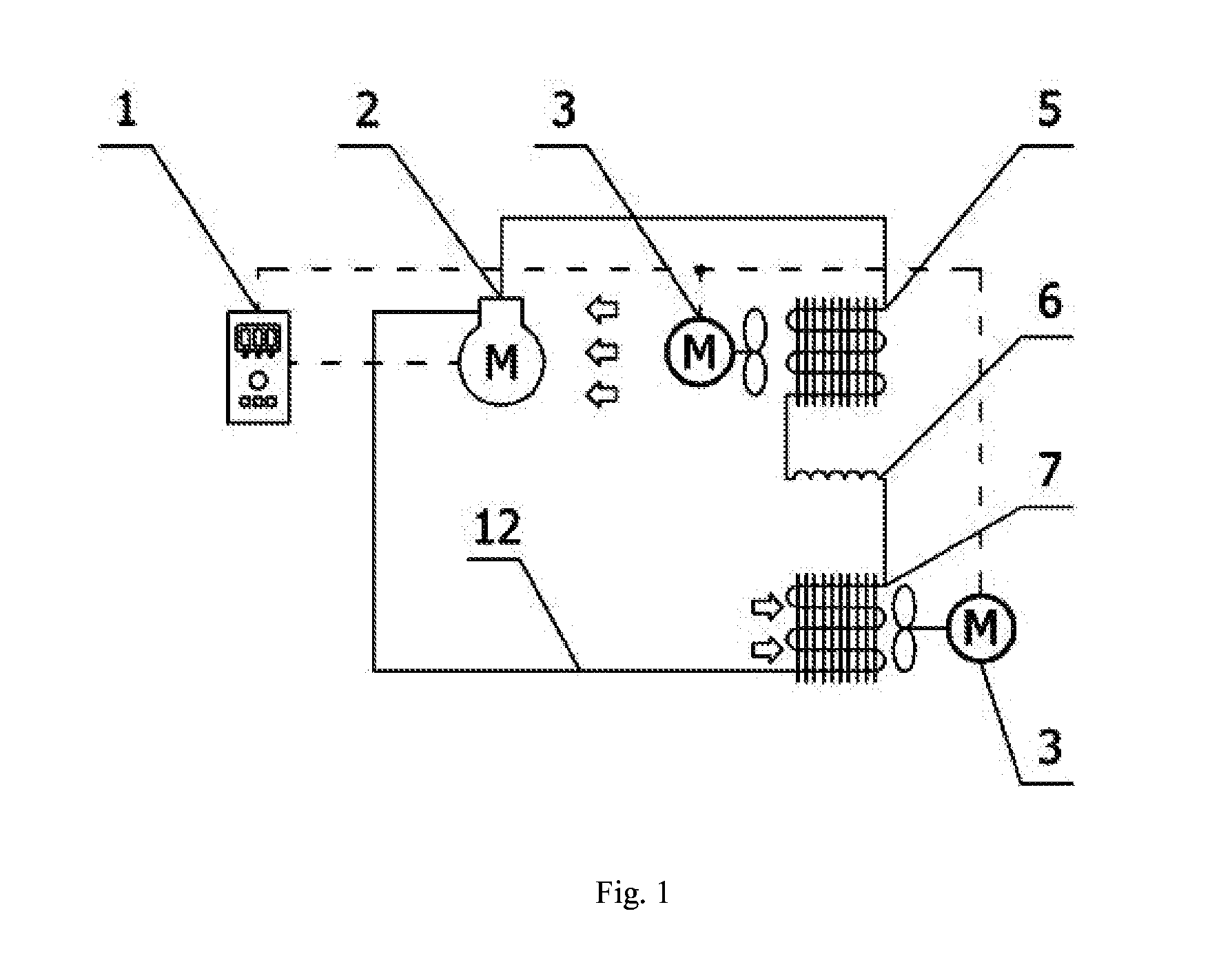
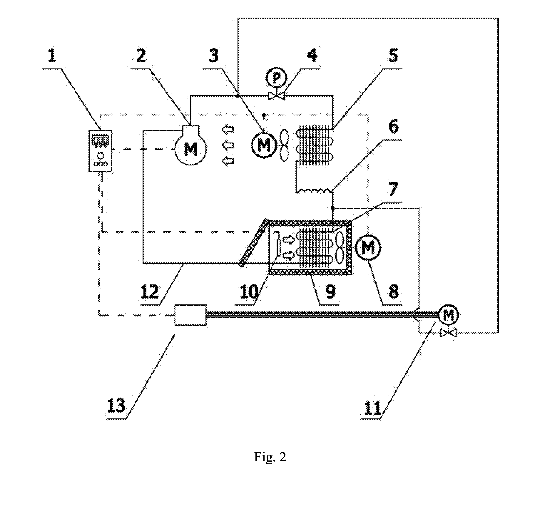
[0040]Operation of the refrigerating capacity control device can be understood by reference first to a traditional refrigerating device as shown in FIG. 1 and then by reference to the current invention as shown in FIG. 2. A refrigerating capacity control device comprises a controller (1), a compressor (2), a condenser fan (3) , a pressure regulating valve (4), a condenser (5) , a throttling device (6), an evaporator (7), circulating fan or pump (8), chamber or bath (9) requiring temperature control, temperature sensor (10), an electronic expansion valve for hot-gas bypassing (11), refrigerating pipelines (12) and a control panel (13) for driving an electronic expansion valve. Wherein, the compressor (2), the condenser (5), the throttling device (6), and the evaporator (7) connected sequentially by refrigerating pipeline (12), condenser fan (3) for the condenser (5) , chamber or bath (9) requiring temperature control and circulating fan or pump (8) for forced convection are parts for...


PUM


Abstract

This invention hereof discloses a refrigerating capacity control device, a test apparatus and a refrigerating control method using the device. The refrigerating capacity control device comprises a compressor (2), a condenser (5), an evaporator (7), a controller (1), a pressure regulating valve (4), a throttling device (6), a control panel (13) for driving a hot-gas valve, and a hot-gas valve (11). The controller is connected with the hot-gas valve (11) through the control panel (13) for driving a hot-gas valve; the pressure regulating valve (1) is disposed between an outlet of the compressor (2) and an inlet of the condenser (5) that are arranged in the refrigerating device; the throttling device (6) is disposed between an outlet of the condenser (5) and an inlet of the evaporator (7); one-end of the hot-gas valve (11) is disposed on a pipeline between the outlet of the compressor (2) and the front end of the pressure regulating valve (4), and the other end thereof is disposed on a pipeline that is between the throttling device (6) and an inlet of the evaporator (7).

Description

FIELD OF THE INVENTION[0001]This invention is related to a hot-gas refrigerating capacity control device for accurate control of refrigerating capacity in climatic and environmental testing equipment. Particularly, this invention makes it possible for the refrigerating system to operate and maintain a temperature close to or higher than ambient temperature with less or no accessory heating. It can decrease the power consumption from additional heating, increase energy efficiency ratio and even eliminate the use of a heater. The control device features in simpler structure and lower energy consumption. It can be used as an important means of accurate temperature control for climatic and environmental testing equipment. Moreover, the invention also relates to a testing apparatus incorporating the refrigerating capacity control device and a control method used in such control device.BACKGROUND OF THE INVENTION[0002]Climatic and environmental testing equipment (such as liquid baths and ...

Claims


Application Information

Patent Timeline
IPC IPC(8): F25B41/04F25B49/02
CPCF25B41/04F25B2600/25F25B49/02F25B2400/0403F25B2400/0411F25B2600/2517F25B41/24Y02B30/70F25B1/00
Inventor XU, YUEMING
Owner XUTEMP TEMPTECH
Learn More