
Emergency shutoff valve

Active Publication Date: 2006-06-13
HALOGEN VALVE SYST
View PDF9 Cites 30 Cited by
  • Summary
  • Abstract
  • Description
  • Claims
  • Application Information

AI Technical Summary

Benefits of technology

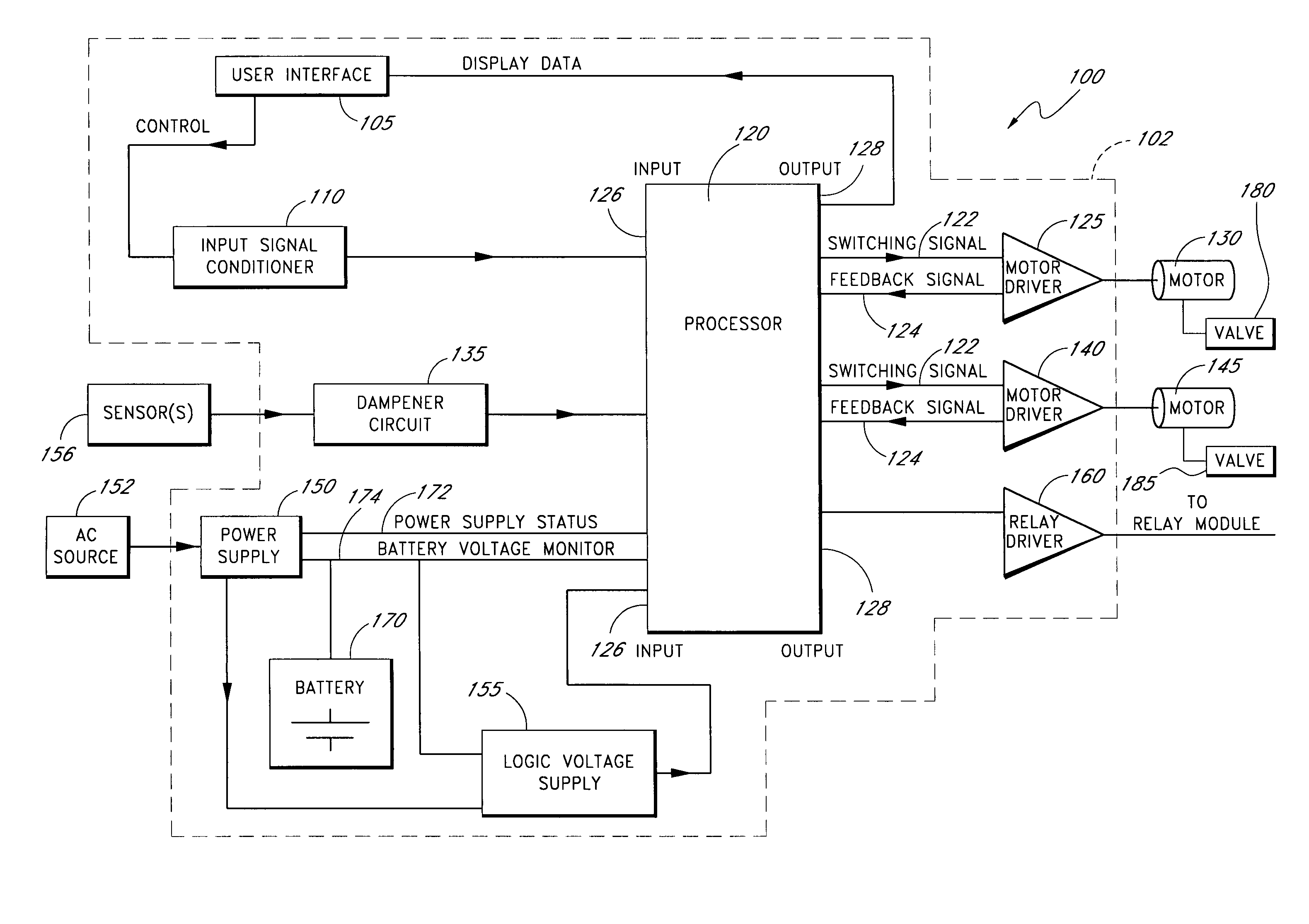
[0008]In accordance with the foregoing, in one embodiment an automatic or remote valve actuation system is provided that can be powered by an “uninterruptable” power supply (for example, a backup or reserve battery) that can be easily replenished from a readily available source, such as a municipal 110 volt alternating current source, thus eliminating the need for a compressed air source. Optionally, the system is portable, and can easily be configured for use with both bulk containers and application containers. The system can be used with both liquid and gas valves on pressurized storage containers. In one embodiment, such a system can be used with a plurality of leak detection sensors which can be placed throughout the facility where toxic chemicals are used, thus providing for emergency shutoff even in the case of a leak remote to the pressurized storage container. Optionally, the system permits manual operation of the valves as well. Advantageously, embodiment of the system can be economically manufactured and can be installed and used without significant training.

Problems solved by technology

Many of these chemicals are immediately toxic to humans, even in low concentrations.
The containers are, however, routinely left unattended for extended periods of time while connected to process piping during filling and dispensing.
Thus, it may take days, weeks, or even months for the contents of such containers to be completely discharged.
In addition, if there is any leakage at the pressurized storage container, or at any other point in the facility where such toxic chemicals are used, the toxicity of the chemicals involved will often preclude the approach of an operator or technician without protective breathing apparatus and protective clothing.
However, once a particular mode of operation, either manual or automatic, is selected by the operator, the alternative mode is effectively disabled.
Disadvantageously, should the manual mode be selected and the system left unattended, emergency shutoff in the automatic mode would not be possible.
Such systems generally are not suitable for use with application container valves.
In addition, compressed air typically requires dehumidification and filtering to avoid freezing, corrosion, and particulate contamination, all of which can damage the system or cause it to malfunction.
Accordingly, compressed air systems are typically quite complex, bulky, and expensive.

Method used


Image

  • Emergency shutoff valve
  • Emergency shutoff valve
  • Emergency shutoff valve

Examples


Embodiment Construction

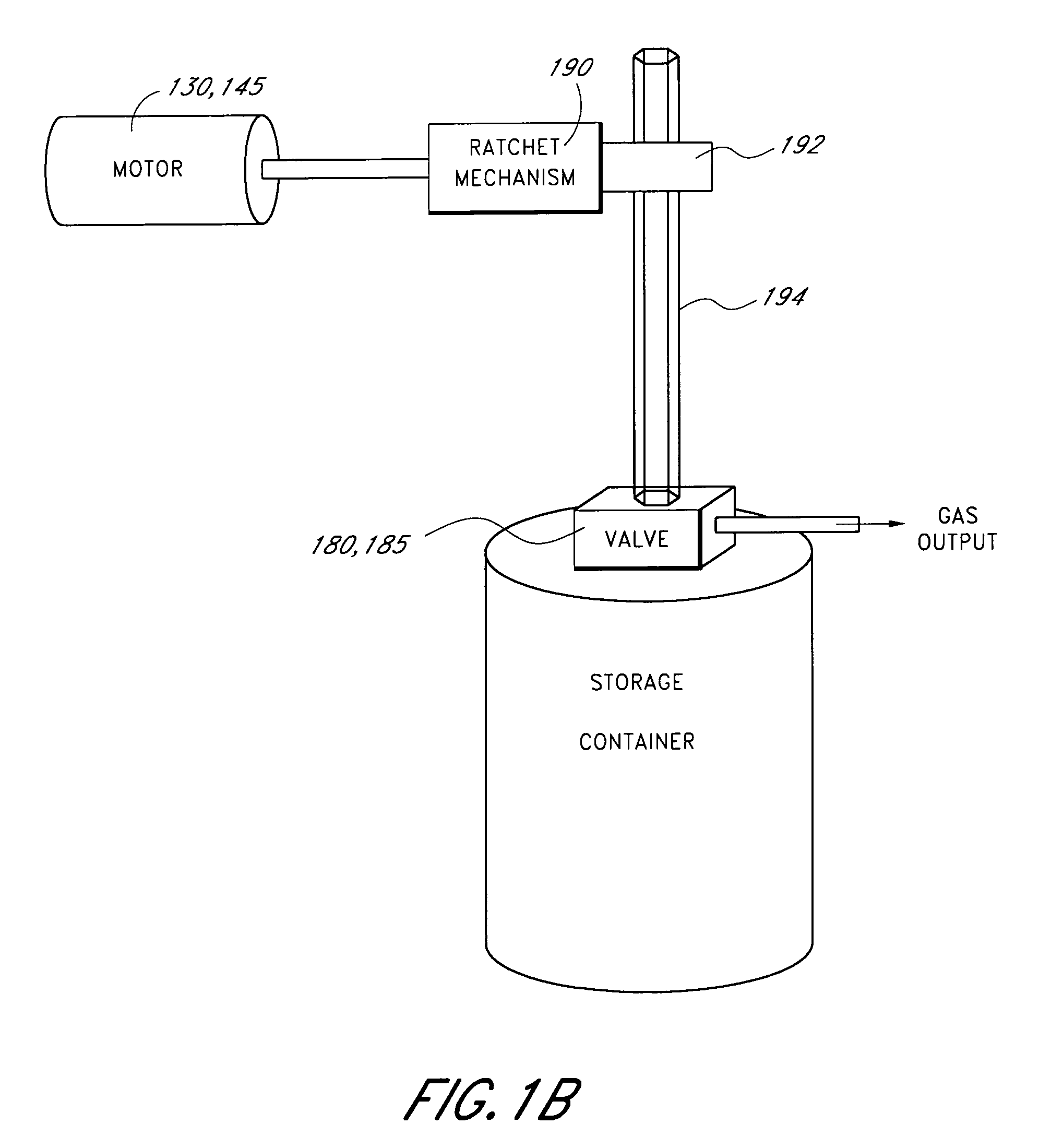
[0018]The various components comprising an exemplary embodiment of an emergency valve closing system 100 are described herein. As will be described in greater detail below, the valve closing system 100 can be used to automatically or manually close valves, such as multi-turn self seating valves, such as are often found on pressurized storage containers. The valve closing system can be used with both gas and liquid valves. In one embodiment, a processor based solid state electronic controller receives valve closing commands from either a user interface or from external sensors, and then closes one or more attached valves to a predetermined torque. The processor can comprise a processor, a microcontroller, or another suitable solid state electronic controller. In other embodiments, other control devices, such as a state machine, can be used in place of, or in addition to, the microprocessor.

Hardware Overview

[0019]FIG. 1A illustrates an exemplary embodiment of an emergency valve closin...


PUM


Abstract

A valve control system comprises a programmable electronic controller. The programmable electronic controller is configured to provide an emergency actuation signal to a motor upon receiving an emergency close signal. The programmable electronic controller is configured to provide a test actuation signal to the motor upon receiving a test close signal. The valve control system further comprises a gas detection input configured to receive a gas detection signal. Receipt of the gas detection signal at least partially meeting a first criterion causes the emergency close signal to be supplied to the controller. The valve control system further comprises a user interface configured to provide the controller with the test close signal in response to a user input. The valve control system further comprises a low battery input configured to receive a low battery signal. Receipt of the low battery signal causes the emergency close signal to be supplied to the controller.

Description

PRIORITY APPLICATION[0001]This application claims priority under 35 U.S.C. § 119(e) from U.S. Provisional Patent Application Ser. No. 60 / 367,943, entitled “Emergency Valve Closing Apparatus” and filed Mar. 26, 2002. The entire disclosure of this priority document is hereby incorporated by reference in its entirety.FIELD OF THE INVENTION[0002]The present invention relates generally to the field of valve actuation devices, and relates specifically to an electronically controlled valve actuation system.BACKGROUND OF THE INVENTION[0003]Hazardous or toxic chemicals, such as chlorine, sulfur dioxide and ammonia, are widely distributed in pressurized containers for use in water purification, sewage treatment, and a variety of other industrial and agricultural applications. Many of these chemicals are immediately toxic to humans, even in low concentrations. Accordingly, it is commonplace for the containers, valves, fittings and dispensing procedures for these chemicals to be strictly regula...

Claims


Application Information

Patent Timeline
IPC IPC(8): F16K17/38
CPCF16K31/046F16K37/0083F16K37/0091Y10T137/0396Y10T137/1939Y10T137/8175
Inventor KINCAID, THOMAS R.SHIVERS, JAMES S.MOSHER, FREDERICK A.
Owner HALOGEN VALVE SYST
Learn More