
Stage system including fine-motion cable unit, exposure apparatus, and method of manufacturing device

a technology of stage system and cable unit, which is applied in the field of stage system, can solve the problems of difficult to realize a stage movable in a long stroke in terms of machining ability, and the positioning accuracy of the fine-motion stage is decreasing, so as to achieve long strokes, high-precision positioning, and low cost.

Inactive Publication Date: 2006-06-06
CANON KK
View PDF10 Cites 6 Cited by
  • Summary
  • Abstract
  • Description
  • Claims
  • Application Information

AI Technical Summary

Benefits of technology

The present invention provides a stage system that can perform high-precision positioning by reducing disturbances caused by cables, such as power cables, sensor cables, or vacuum cables. The system includes a substrate stage movable in at least two axial directions, a fine-motion cable unit that holds a cable connected to the substrate stage and is movable in a short stroke in at least two axial directions, and a coarse-motion cable unit for moving the fine-motion cable unit in a long stroke in at least one axial direction. The fine-motion cable unit may follow the substrate stage, reducing disturbances to the fine-motion stage. The coarse-motion cable unit and the coarse-motion stage can be integrated together, simplifying the system and reducing errors. The cable is fixed to the coarse-motion cable unit, reducing disturbances caused by variations in the relative positions of the coarse-motion stage and the substrate stage. The substrate stage can be movable in three or six axial directions, and the fine-motion cable unit can follow the substrate stage in the three or six axial directions. The coarse-motion cable unit and / or the coarse-motion stage can be guided by a contact guide, achieving inexpensive, high-precision positioning.

Problems solved by technology

This causes disturbances to the fine-motion stage, thus decreasing positioning accuracy of the fine-motion stage.
Moreover, for controlling the position of the cable-holding stage or the coarse-motion X-Y stages by means of the airslider (mentioned above), with great accuracy, it is difficult to realize a stage movable in a long stroke in terms of machining ability.

Method used


Image

  • Stage system including fine-motion cable unit, exposure apparatus, and method of manufacturing device
  • Stage system including fine-motion cable unit, exposure apparatus, and method of manufacturing device
  • Stage system including fine-motion cable unit, exposure apparatus, and method of manufacturing device

Examples


first embodiment

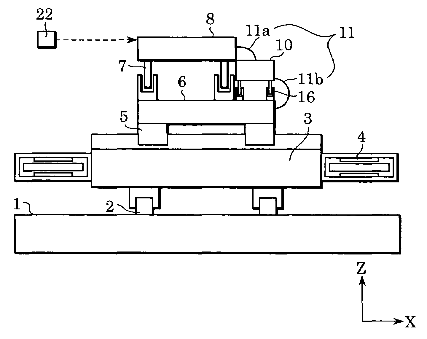
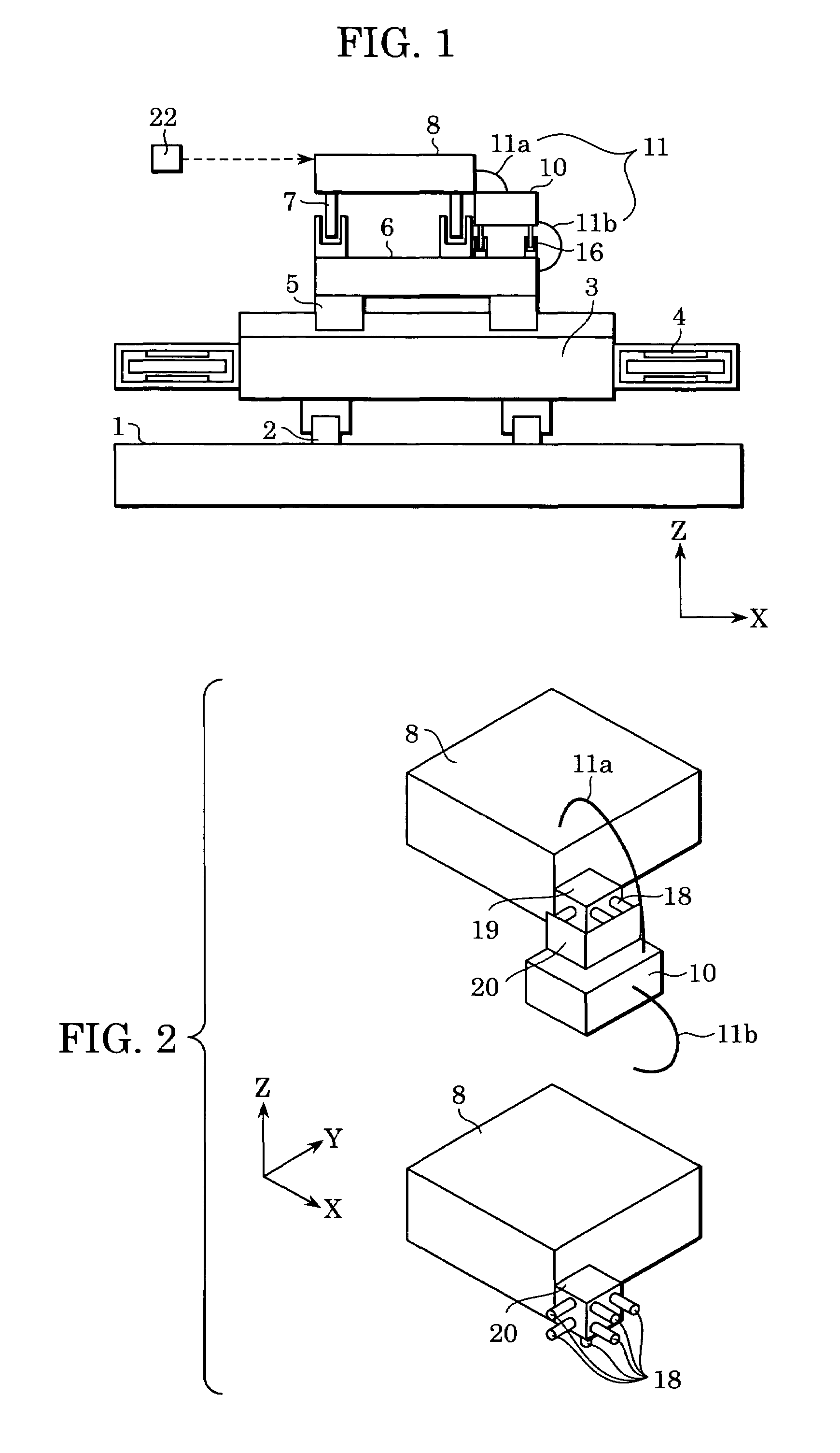
[0033]FIG. 1 shows a stage system according to a first embodiment of the present invention. In FIG. 1, a Y stage 3, being a coarse-motion stage in the Y direction, is guided by linear motor (hereinafter referred to as LM) guides 2 fixed on a base table 1 so as to be slidably supported in the Y direction. Y linear motors 4 are disposed on both sides of the Y stage 3 so that the Y stage 3 moves in a long stroke (coarse motion) in the Y direction.

[0034]LM guides 5 are disposed on the Y stage 3 to guide an X stage 6, being a coarse-motion stage in the X direction. Therefore, the X stage 6 is slidably supported by the LM guides 5 in the X direction with respect to the Y stage 3. The X stage 6 is equipped with an X linear motor (not shown) so as to be movable in a long stroke in the X direction.

[0035]In this embodiment, the LM guides 5 for the X stage 6 and the LM guides 2 for the Y stage 3 are of the LM guide type (e.g., rolling guides), which is inexpensive, has high stiffness, and is o...

second embodiment

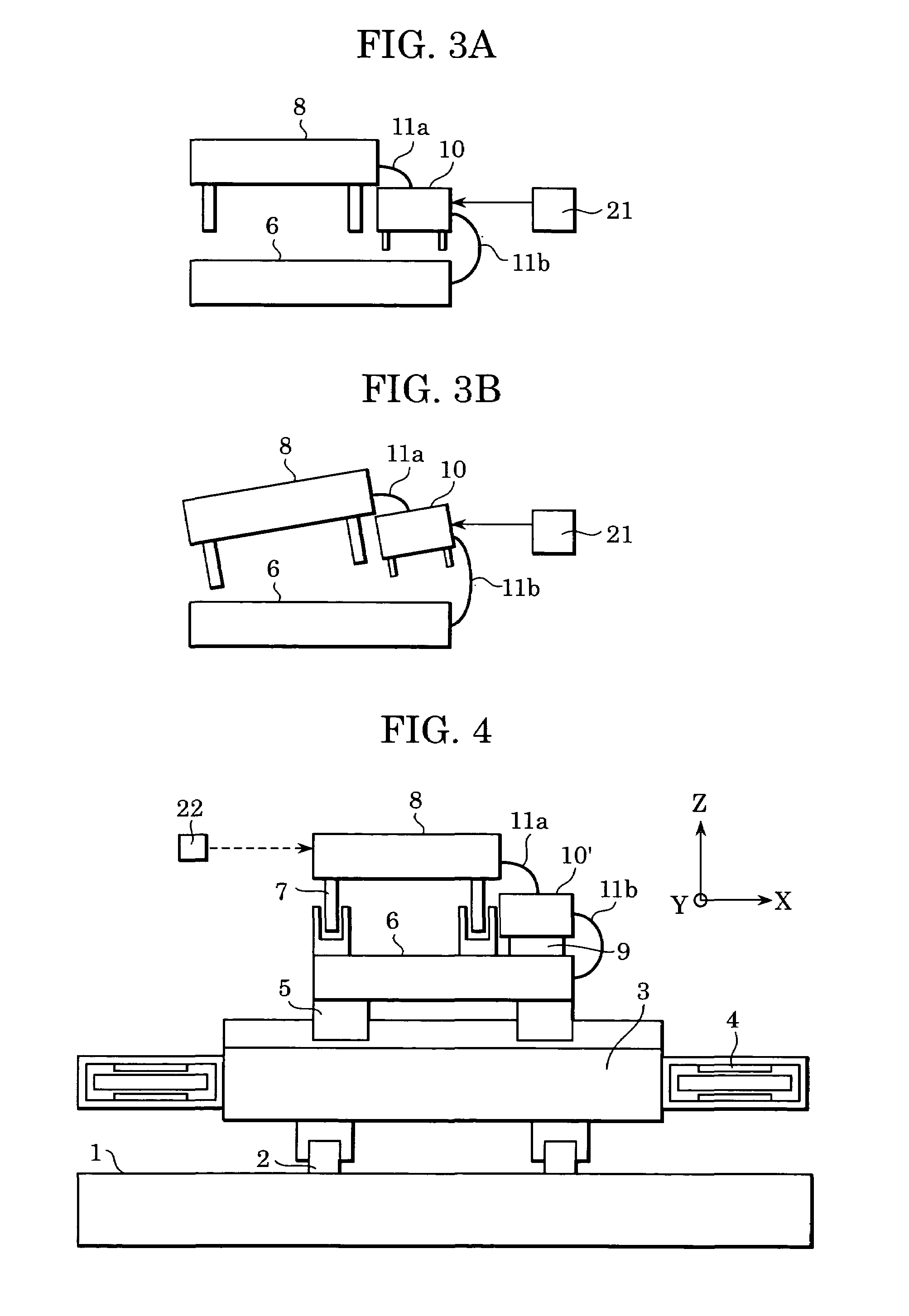
[0051]FIG. 4 shows an embodiment in which the fine-motion cable unit 10 of the first embodiment is made movable, finely, in three axial directions. The same reference numerals have been retained for similar parts, which have the same structures as those of the first embodiment, and explanations thereof are omitted.

[0052]FIGS. 5A to 5C show details of a fine-motion cable unit 10′, which is shown in FIG. 4. A magnet unit 10b is supported directly above the X stage 6 so as to be slidable in the X, Y, and θ directions. As illustrated in FIG. 5A, the magnet unit 10b, which is a fine-motion cable unit or a fine-motion cable stage, consists of yokes 13 / 14 and three pairs of magnets 12 that are magnetized in the Z direction and are fixed to the yokes 15. As shown in FIG. 5B, a coil plate 10a, which will be described below, is sandwiched between the magnets 12 in the vertical (Z) direction.

[0053]As shown in FIG. 5A, each pair of the magnets 12 consists of one magnet component in which the no...

third embodiment

[0058]FIG. 6 shows a third embodiment in which the stage system of the second embodiment is applied in a non-atmospheric environment, such as in a vacuum. A major difference in this embodiment is that an exhaust slot 17 is arranged around an air pad 9 supporting the magnet unit 10b of the fine-motion cable unit.

[0059]In FIG. 6, the same reference numerals have been retained for similar parts which have the same structures shown in FIG. 5C, and explanations thereof are omitted. In this embodiment, the exhaust slot 17 arranged around the air pad 9 is connected to an external pump with piping (not shown) therebetween. Gas emitted from the air pads 9 is retrieved by a pump (not shown) to prevent the gas from leaking to a vacuum atmosphere around the stage system.

[0060]Additionally, in order to avoid outgassing, a grease applicable to vacuum conditions may be used in the LM guides 5 (see FIG. 4) of the X stage 6, or surface treatment for vacuum conditions may be performed on stage compon...


PUM

PropertyMeasurementUnit
distanceaaaaaaaaaa
static pressureaaaaaaaaaa
pressureaaaaaaaaaa

Abstract

A stage system that reduces disturbances caused by deformation of a cable and achieves high-precision positioning. The stage system includes a substrate stage movable in at least two axial directions, a fine-motion cable unit that holds a cable and finely moves in at least two axial directions, and a coarse-motion cable unit that coarsely moves the fine-motion cable unit in at least one axial direction.

Description

[0001]This application claims priority from Japanese Patent Application No. 2003-204674 filed Jul. 31, 2003, which is hereby incorporated by reference.BACKGROUND OF THE INVENTION[0002]1. Field of the Invention[0003]The present invention relates to stage systems, and preferably, to a stage system installed in an exposure apparatus for manufacturing a semiconductor device.[0004]2. Description of the Related Art[0005]An exposure apparatus used during the manufacture of a device, such as a semiconductor device, or a liquid crystal device, has a stage system for moving a master plate, such as a mask, a reticle, or a substrate subjected to exposure, such as a semiconductor wafer, or a glass substrate (hereinafter, they are collectively called a substrate).[0006]Such a stage system is disclosed in, for example, Japanese Patent Laid-Open No. 2000-106344A (See FIG. 11). Referring to FIG. 11, a yaw guide 550 and a Y stage 551 are disposed on a base table 502. The yaw guide 550 and the base ta...

Claims


Application Information

Patent Timeline
Patent Type & Authority Patents(United States)
IPC IPC(8): G03B27/58G03B27/62B23Q1/00G03F7/20H01L21/027
CPCG03F7/70758G03F7/70716
Inventor KORENAGA, NOBUSHIGE
Owner CANON KK
Learn More