
Automotive alternator having cooling fan coupled to rotor shaft

a technology of alternators and cooling fans, which is applied in the direction of liquid fuel engines, magnetic circuit rotating parts, magnetic circuit shapes/forms/construction, etc., can solve the problems of failure to successfully perform welding between the cooling fan and the fan base, and the cooling fan may not be correctly positioned in the rotational direction, so as to achieve a simple process and facilitate connection

Active Publication Date: 2006-06-06
DENSO CORP
View PDF9 Cites 9 Cited by
  • Summary
  • Abstract
  • Description
  • Claims
  • Application Information

AI Technical Summary

Benefits of technology

[0008]The present invention has been made in view of the above-mentioned problems, and an object of the present invention is to provide an improved alternator, in which a cooling fan is easily connected to a rotor shaft at a right position in a simple process.

Problems solved by technology

In the alternator proposed by JP-Y2-5-8781, however, the cooling fan may not be correctly positioned in the rotational direction though it can be coaxially connected to the rotor shaft.
If the cooling fan is not correctly positioned in the rotational direction relative to the fan base or the pole core, welding between the cooling fan and the fan base may not be successfully performed.

Method used


Image

  • Automotive alternator having cooling fan coupled to rotor shaft
  • Automotive alternator having cooling fan coupled to rotor shaft
  • Automotive alternator having cooling fan coupled to rotor shaft

Examples


Embodiment Construction

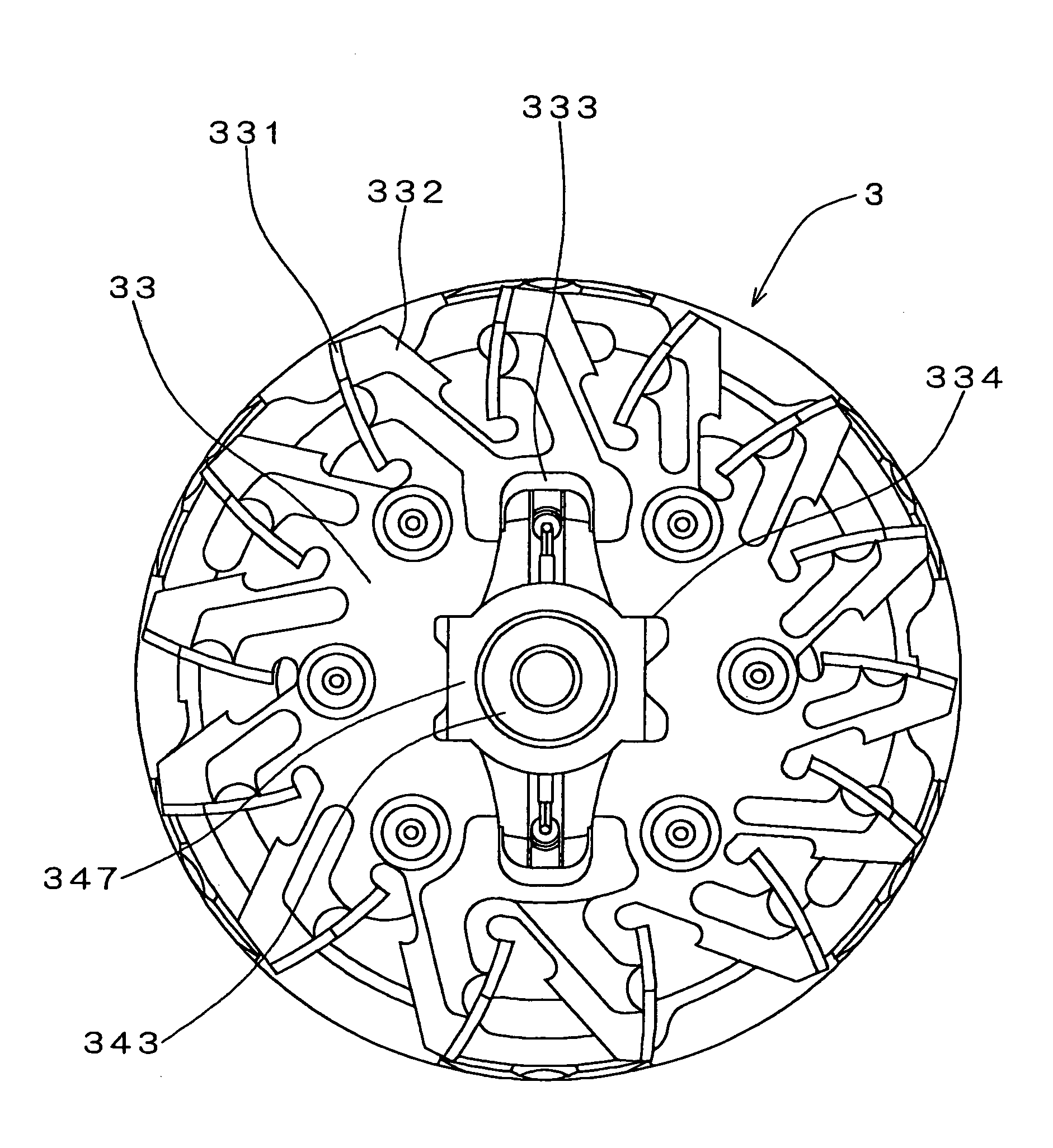
[0019]A preferred embodiment of the present invention will be described with reference to accompanying drawings. As shown in FIG. 1, an alternator 1 for use in an automotive vehicle is composed of: a stator 2 having an armature winding 21; a rotor 3 having a filed winding 31 wound on pole cores 30; a cooling fan 32 connected to the front side of the rotor; a cooling fan 33 connected to the rear side of the rotor; a fan base 36 disposed between an rear end of the pole core 30 and the cooling fan 33; a front housing 41; a rear housing 45; a brush device 5 for supplying electric current to the field winding 31; a voltage regulator 6 for controlling an output voltage to a predetermined voltage; a rear cover 7 covering and protecting the brush device 5 and the voltage regulator 6; a pulley 9 driven by an engine for driving the rotor 3; and other associated components.

[0020]The stator 2 is held between the front housing 41 and the rear housing 45, and the rotor 3 is rotatably supported in...


PUM


Abstract

An alternator for use in an automobile includes a stator supported between a front housing and a rear housing, and a rotor connected to a rotor shaft and rotatably supported inside the stator. A cooling fan is positioned at an end of a pole core of the rotor. The cooling fan is coupled to the rotor shaft by engaging edges of a center opening of the cooling fan with a non-circular flange formed on the rotor shaft. The cooling fan is correctly positioned relative to the rotor shaft, without using a jig, both in the radial direction and in the rotational direction of cooling fan. Noises and vibrations due to rotational imbalance of the cooling fan are suppressed.

Description

CROSS-REFERENCE TO RELATED APPLICATION[0001]This application is based upon and claims benefit of priority of Japanese Patent Application No. 2004-189055 filed on Jun. 28, 2004, the content of which is incorporated herein by reference.BACKGROUND OF THE INVENTION[0002]1. Field of the Invention[0003]The present invention relates to an alternator used in an automotive vehicle.[0004]2. Description of Related Art[0005]In a conventional alternator, a cooling fan connected to a rotor shaft generates airflows in an axial direction for cooling a field winding and in a radial direction for cooling coil ends of an armature winding. In some alternators, a fan base for rectifying directions of the airflows is disposed between an end of a pole core and the cooling fan. JP-B2-3497896 discloses such an alternator that includes a slip-ring molded together with terminals for electrically connecting a slip-ring to a field winding. In this alternator, a rotor shaft is forcibly inserted into a center hol...

Claims


Application Information

Patent Timeline
Patent Type & Authority Patents(United States)
IPC IPC(8): H02K9/06F04D29/28F04D29/62H02K7/00H02K9/00H02K9/28H02K13/02
CPCF04D29/282F04D29/626H02K13/02H02K9/06H02K9/28H02K7/003
Inventor ISHIDA, HIROSHIICHIKAWA, MASAO
Owner DENSO CORP
Learn More