Actuating and sensing device for scanning probe microscopes
a scanning probe and sensing device technology, applied in scanning probe microscopy, surface/boundary effect, instruments, etc., can solve the problem of difficult to use very soft cantilevers for dynamic mode measurements in air, cantilever chips and piezo slabs are not effective at higher frequencies, and can only provide sufficient excitation to the tip. , to achieve the effect of less often damaged during operation
- Summary
- Abstract
- Description
- Claims
- Application Information
AI Technical Summary
Benefits of technology
Problems solved by technology
Method used
Image
Examples
first embodiment
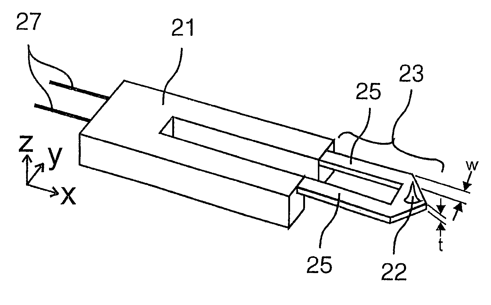
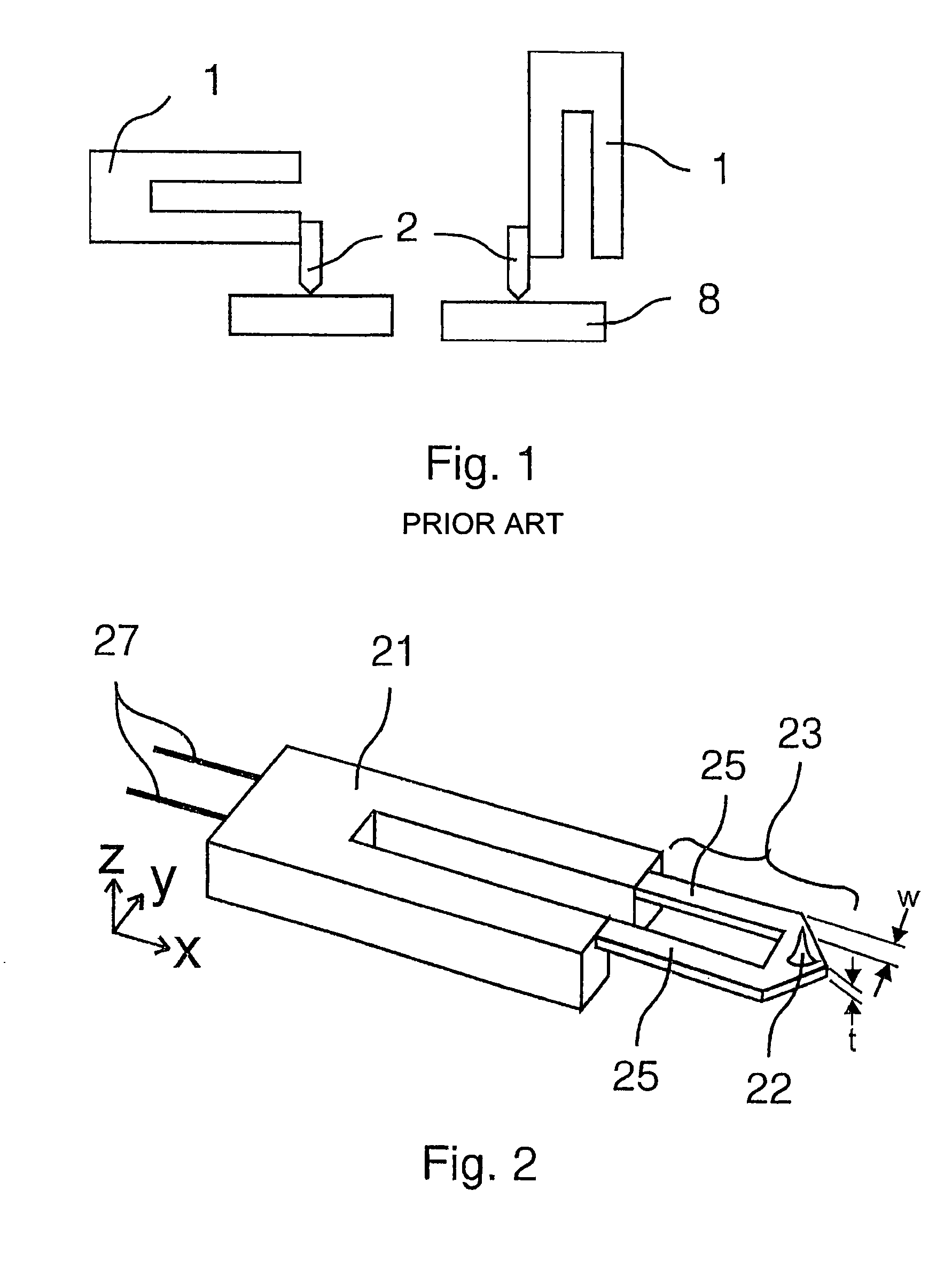
[0046]FIG. 11 represents a top and side view of an actuating and sensing device, wherein the tip 202 is connected to the tuning fork 201 via the connection means 203 in three points. The connection means, with its front part formed as a U- or V-shaped plate spring 203, is attached (glued or bonded) to the different prongs 206 of the tuning fork 201 and additionally to the base 207 of the tuning fork 201. The front part of the plate spring 203 with the tip 202 is designed and can be moved in the same manner as described in the first embodiment in FIG. 2. The legs 205 of the spring plate 205 each comprise first connection points formed as enlarged areas 208a,b, with which the legs are attached to one prong each. With a further connection point the legs are attached to the base 207 of the tuning fork. This further connection point is also formed as an enlarged area 209 connecting the legs 205 but without preventing the movement of the prongs 206. The plate spring 203 is electrically is...
fifth embodiment
[0048]In FIG. 12, a top and side view of another embodiment of an actuating and sensing device with the tip 302 connected to the tuning fork in three points is shown. This embodiment is especially designed for the use in a scanning near field optical microscope or any microscope where a direct and / or straight connection from the base of a tuning fork to the tip 302 is needed or preferred. A front part of the connection means, formed as a U- or V shaped plate spring 303, is in general designed and can be moved in a same manner as described in the first or fifth embodiment in FIGS. 2 and 11, respectively. The two legs 305 of the plate spring 303 are attached to the two prongs 306 of the tuning fork in first connection points 308a,b. From the tip region of the plate spring 303 a connection part 310, similar to a third leg, leads to the base 307 of the tuning fork. This connection part 310 is fixed to the base 307 of the fork in a further connection point 309 and extends over the whole ...
PUM
| Property | Measurement | Unit |
|---|---|---|
| width | aaaaa | aaaaa |
| total length | aaaaa | aaaaa |
| resonance frequencies | aaaaa | aaaaa |
Abstract
Description
Claims
Application Information
 - R&D
- Intellectual Property
- Life Sciences
- Materials
- Tech Scout
- Unparalleled Data Quality
- Higher Quality Content
- 60% Fewer Hallucinations
Browse by: Latest US Patents, China's latest patents, Technical Efficacy Thesaurus, Application Domain, Technology Topic, Popular Technical Reports.
© 2025 PatSnap. All rights reserved.Legal|Privacy policy|Modern Slavery Act Transparency Statement|Sitemap|About US| Contact US: help@patsnap.com


