
Resistance substrate and variable resistor

a resistance substrate and variable resistor technology, applied in the direction of resistor details, adjustable resistors, resistors with sliding contact, etc., can solve the problems of inability to meet the needs of different types of molds, inconvenient design and production, and high cost of multiple types of molds, so as to achieve easy variation and increase the resistance range.

Active Publication Date: 2006-05-23
MURATA MFG CO LTD
View PDF9 Cites 2 Cited by
  • Summary
  • Abstract
  • Description
  • Claims
  • Application Information

AI Technical Summary

Benefits of technology

[0009]To overcome the problems described above, preferred embodiments of the present invention provide a resistance substrate and a variable resistor having a structure such that a variable resistance range can be increased and can be easily varied.
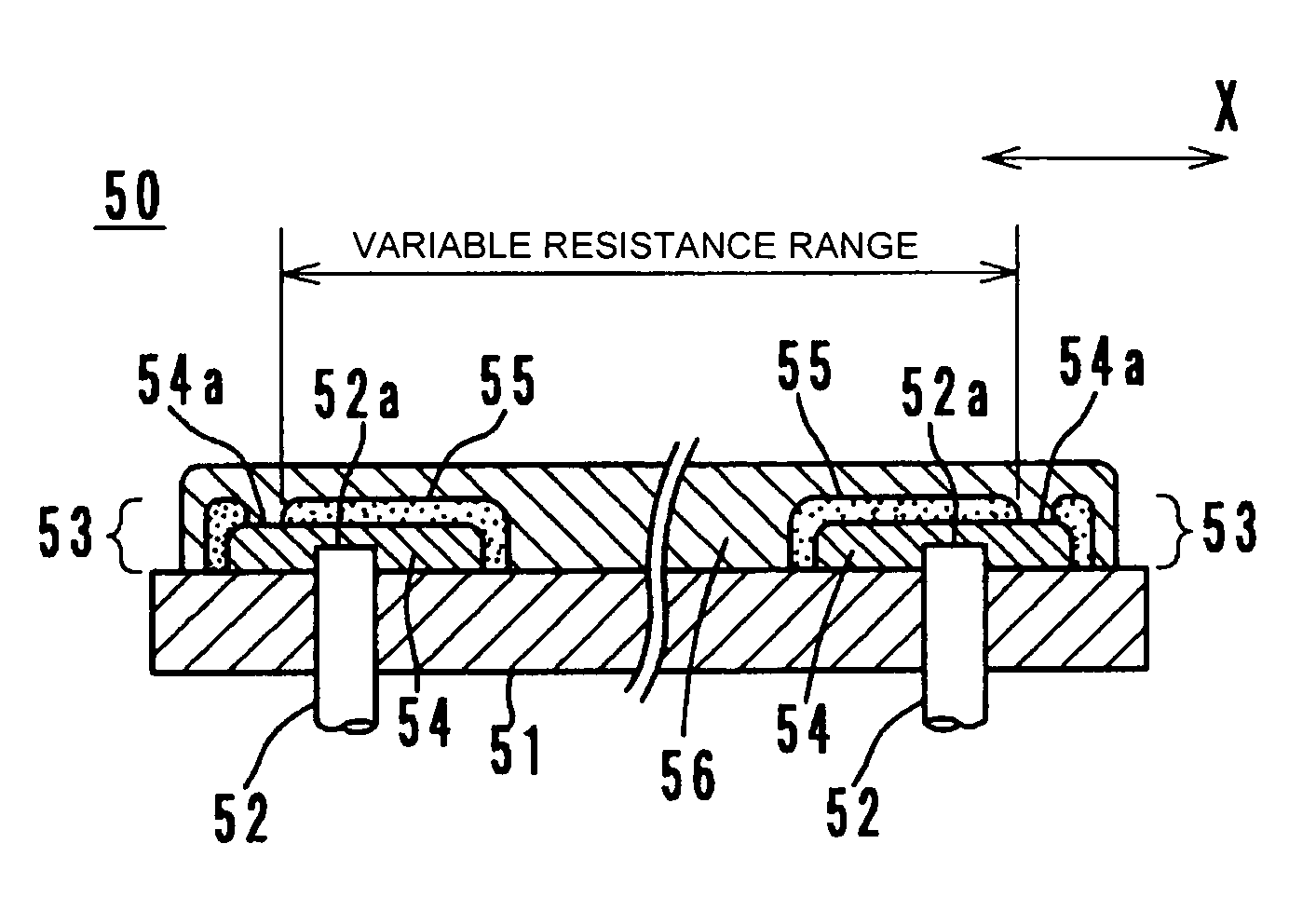
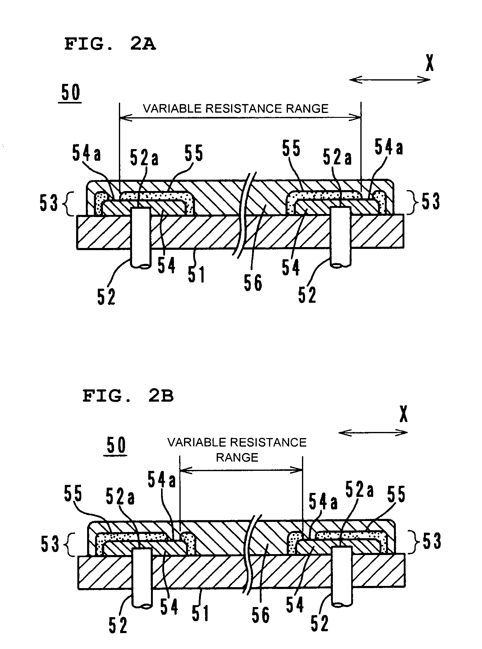
[0011]In the resistance substrate according to a preferred embodiment of the present invention, the exposed portions of the two electrodes which are not covered by the insulator film are electrically connected to each other via the resistor element. Accordingly, a variable resistance range can be increased by simply changing the locations of the exposed portions, that is, by changing the location at which the insulator film for covering the conductive elements is formed. In addition, the variable resistance range can be varied. Accordingly, unlike the known structure, it is not necessary to form the terminals by a punching process using various types of molds, and various types of resistance substrates and variable resistors having different variable resistance ranges are easily manufactured.
[0012]In addition, according to a preferred embodiment of the present invention, a variable resistor includes the above-described resistance substrate and a slider slidable along a surface of the resistor element. The resistor element preferably has a substantially annular shape with a cutout portion. With this structure, rotary variable resistors in which resistances are adjusted depending on the rotational locations of sliders and which have increased or different variable resistance ranges can be easily manufactured.
[0013]In addition, a maximum angle between lines extending from the center of the resistor element through the exposed portions of the electrodes may be set to be less than a maximum angle between lines extending from the center of the resistor element through the exposed portions of the metal terminals in a region including the cutout portion. With this structure, the length of the substantially annular resistor element can be increased without changing the shapes and locations of the metal terminals. Accordingly, the variable resistance range can be increased.

Problems solved by technology

However, this is not practical since it is difficult, time consuming and expensive to design and produce multiple types of molds.
This problem is not limited to rotary variable resistors, and variable resistors having linearly-moving sliders also have a similar problem.
Therefore, there is a limit on the amount that the variable resistance range can be increased.

Method used


Image

  • Resistance substrate and variable resistor
  • Resistance substrate and variable resistor
  • Resistance substrate and variable resistor

Examples


first preferred embodiment

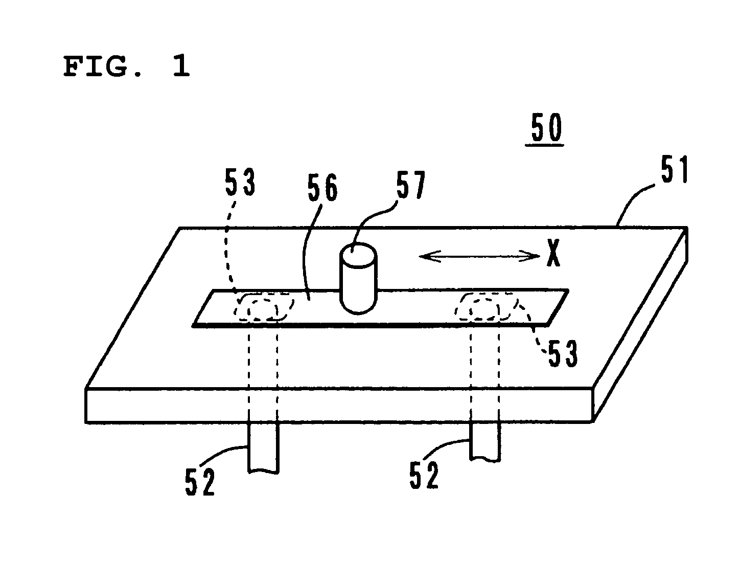
[0029]A resistance substrate according to a first preferred embodiment of the present invention will be described below with reference to FIGS. 1, 2A, and 2B.

[0030]A resistance substrate 50 includes a substrate member 51 made of insulating material, two conductive metal terminals 52, two conductive elements 53, and a resistor element 56.

[0031]Each metal terminal 52 includes an exposed portion 52a at the top, the exposed portion 52a being exposed on a surface of the substrate member 51. Each conductive element 53 includes the exposed portion 52a of the corresponding metal terminal 52 and an electrode film 54 which is electrically connected to the exposed portion 52a and which extends along a direction X in which the resistor element 56 extends. Each electrode film 54 is covered by an insulator film 55 such that an exposed portion 54a of the electrode film 54 is left uncovered.

[0032]The resistor element 56 is obtained by applying a conductive resin material to the surface of the subst...

second preferred embodiment

[0036]A rotary variable resistor according to a second preferred embodiment of the present invention will be described below with reference to FIGS. 3A to 7C.

[0037]As shown in FIGS. 3A, 3B, and 4, a variable resistor 1 includes a substrate member 10, a cover 20, and a rotating shaft 30 having a slider 35, all of which are preferably formed as molded resin components. The substrate member 10 includes a center hole 11, and a first terminal 12 and second terminals 13 are embedded in the substrate member 10.

[0038]The first terminal 12 includes terminal portions 12a projecting from side surfaces of the substrate member 10 and an annular current collector 12b in the central area. The current collector 12b is exposed on the surface of the substrate member 10. The first terminal 12 including the end portions 12a and the current collector 12b is obtained by cutting the first terminal 12 out of a single metal member. Each of the second terminals 13 includes a terminal portion 13a which projec...


PUM


Abstract

A resistance substrate includes a substrate member, two conductive elements provided on the substrate member, and a resistor element provided on the substrate member, the resistor element electrically connecting the conductive elements to each other. Each of the conductive elements includes an exposed portion of a metal terminal and an electrode film, the exposed portion of the metal terminal being exposed on a surface of the substrate member and the electrode film being electrically connected to the exposed portion and extending along a direction in which the resistor element extends. Each of the conductive elements is covered by an insulator film such that an exposed portion of the electrode film is left uncovered. The resistor element is electrically connected to the exposed portions of the electrode films at both ends thereof.

Description

BACKGROUND OF THE INVENTION[0001]1. Field of the Invention[0002]The present invention relates to resistance substrates and variable resistors, and more specifically, to a resistance substrate having a variable resistance between two conductive elements and a variable resistor including a slider which slides along a resistor element provided on a substrate member to adjust a resistance.[0003]2. Description of the Related Art[0004]A rotary variable resistor including a slider which slides along a resistor element to adjust a resistance is disclosed in Japanese Unexamined Patent Application Publication No. 2003-124009. FIG. 8 shows a manufacturing step of this variable resistor, in which a substrate member 10 is formed on a hoop material 40 by resin molding, the hoop material 40 being formed into a shape corresponding to terminals by a punching process. FIG. 9 shows a state in which a substantially annular resistor element 15 is formed on the substrate member 10 and metal terminals 12 ...

Claims


Application Information

Patent Timeline
Patent Type & Authority Patents(United States)
IPC IPC(8): H01C10/30
CPCH01C10/38H01C10/30
Inventor HASEGAWA, NAOTAKE
Owner MURATA MFG CO LTD
Learn More