
Chip film fixed resistor with resistance of 10-1Momega

A fixed resistance and range technology, applied in the field of electronic devices, can solve the problems of large resistance deviation, circuit damage, high failure rate of resistors, etc., and achieve the effect of large resistance range, good moisture resistance and high temperature resistance

Inactive Publication Date: 2014-12-31
天津市三环电阻有限公司
View PDF3 Cites 1 Cited by
  • Summary
  • Abstract
  • Description
  • Claims
  • Application Information

AI Technical Summary

Problems solved by technology

[0003] Thin film resistors are mainly used in precision electronic circuits, but due to volume limitations, the structure of the metal film and the electrodes in the resistor needs to be accurately calculated, and, in order to increase the applicability of the resistor, its resistance range needs a larger span, so To ensure the reliability of its use, but the existing chip type thin film fixed resistor has a high failure rate, and what is more serious is that the resistance value deviation is large, which is easy to cause damage to the circuit
[0004] After searching, no patent documents related to the content of this patent were found

Method used

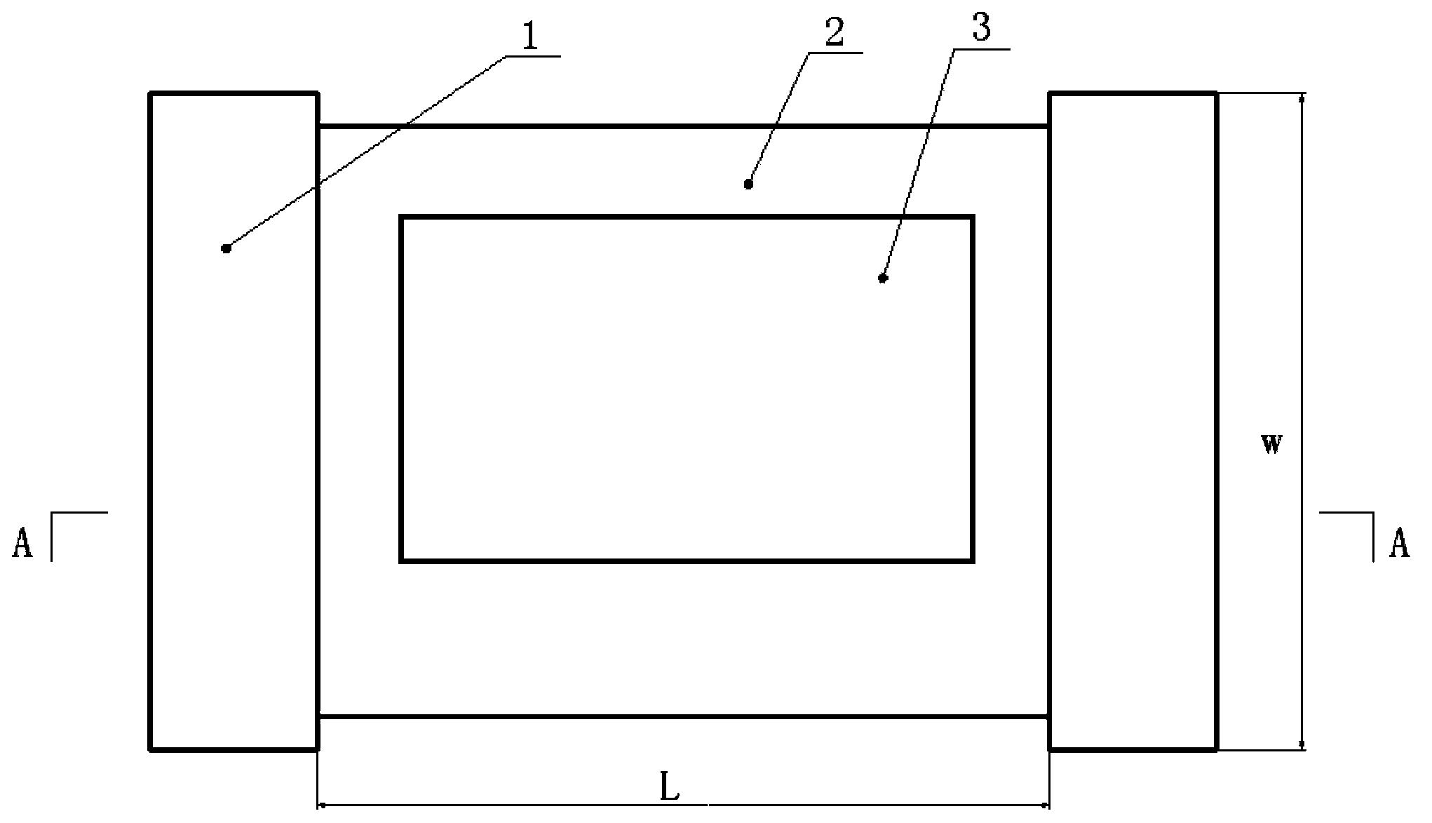
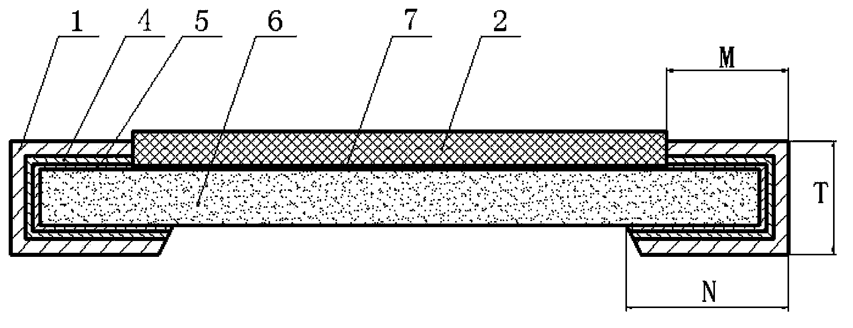

Image

  • Chip film fixed resistor with resistance of 10-1Momega
  • Chip film fixed resistor with resistance of 10-1Momega

Examples


Embodiment Construction

[0015] The present invention will be further described in detail below in conjunction with the accompanying drawings and through specific embodiments. The following embodiments are only descriptive, not restrictive, and cannot limit the protection scope of the present invention.

[0016] A chip-type film fixed resistor with a resistance value ranging from 10 to 1 MΩ, including a substrate 6, a metal resistance layer 7, an inner electrode layer 5, an outer electrode layer 1, and a protective layer 2, and a metal resistance layer is installed in the middle of the upper surface of the substrate, The metal resistance layer is a metal thin film, and the inner electrode layer is mirror-symmetrically coated on the substrate on both sides of the metal resistance layer. Both inner electrode layers are connected with the metal resistor body, and each inner electrode layer is covered with an outer electrode layer. , a nickel alloy layer 4 is installed between each inner electrode layer an...


PUM


Abstract

The invention relates to a chip film fixed resistor with the resistance of 10-1Momega. The chip film fixed resistor includes a substrate, a metal resistance layer, inner electrode layers, outer electrode layers and a protection layer, the middle portion of the upper surface of the substrate is provided with the metal resistance layer, the substrate at two sides of the metal resistance layer is coated with the inner electrode layers in a mirror symmetry manner, the two inner electrode layers are connected with the metal resistance layer, the inner electrode layers are coated with the outer electrode layers respectively, the width of the protection layer is 4.8-5mm, the width of a surface electrode layer is 0.58-0.6mm, the width of a back electrode layer is 0.58-0.6mm, the length of each of the outer electrode layers is 3-3.2mm, and the height of each of the outer electrode layers is 0.6-0.8mm. The resistance of the chip film fixed resistor is controlled in a range of 10-1Momega through effectively regulating the surface electrode layer, the back electrode layer and the dimensions of the outer electrode layers without changing the material or the thickness of the metal resistance layer, has good moisture and high temperature resistance, and is very suitable for precise electronic circuits.

Description

technical field [0001] The invention belongs to the field of electronic devices, and relates to a resistor, in particular to a chip-type film fixed resistor with a resistance value ranging from 10 to 1 MΩ. Background technique [0002] The development direction of resistors is miniaturization and high reliability, so the application field of wirewound resistors is becoming more and more limited, and it is replaced by more and more carbon film or metal film resistors, among which chip metal film fixed resistors More and more popular, according to the difference of resistance value and application field, metal film resistors are divided into thick film and thin film resistors. [0003] Thin film resistors are mainly used in precision electronic circuits, but due to volume limitations, the structure of the metal film and the electrodes in the resistor needs to be accurately calculated, and, in order to increase the applicability of the resistor, its resistance range needs a lar...

Claims


Application Information

Patent Timeline
Patent Type & Authority Applications(China)
IPC IPC(8): H01C7/20H01C1/142
Inventor 李志珣
Owner 天津市三环电阻有限公司
Learn More