
Motorcycle including a unique frame and drive unit

Inactive Publication Date: 2006-05-23
PARADIGM TECH
View PDF21 Cites 11 Cited by
  • Summary
  • Abstract
  • Description
  • Claims
  • Application Information

AI Technical Summary

Benefits of technology

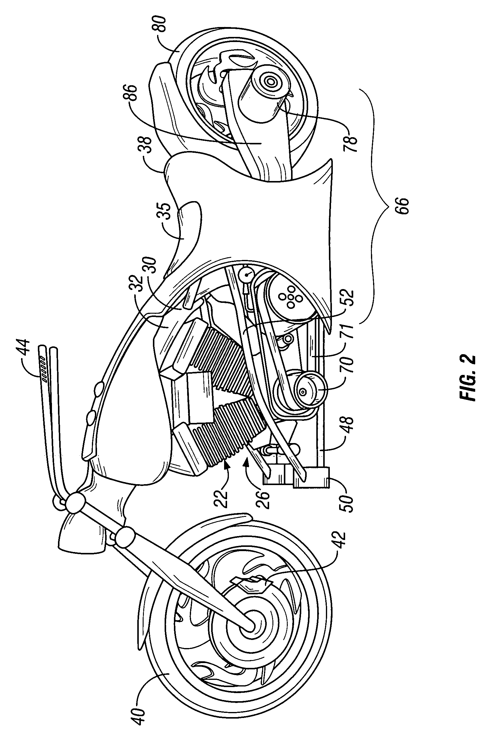
[0017]The hydraulic pump is powered by the power plant of the motorcycle. The hydraulic pump pressurizes the fluid and transfers it via hydraulic lines to a motor including a gear case that steps up the speed of the generally low-speed hydraulic pump. Slowing down or stopping the flow of hydraulic fluid will cause the gearing system to slow down, thus using the motor as a braking system. The use of the hydraulic drive unit of the present invention provides both power and braking to the rear wheel, thereby alleviating the need for a supplemental braking system such as the currently employed brake pads and shoes.
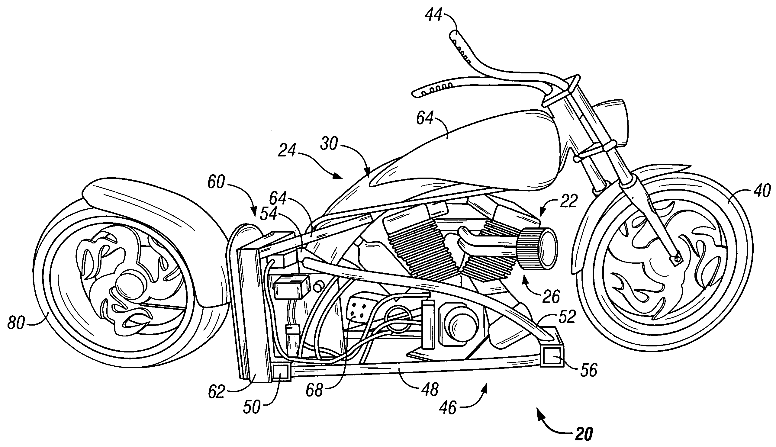
[0018]Moreover, in accordance with the present invention, the power plant and hydraulic drive unit are supported by a spine-like frame without the need for additional front support braces. The spine-like frame of the present invention generally includes a tube of metal that is preferably reinforced with a strip a steel or other high-strength material, such as carbon fiber, kevlar, etc. The power plant and hydraulic pump are secured to an engine carrier that is secured to the spine, thereby simplifying removal of the power plant and hydraulic pump. The power plant thus becomes a structural member that is secured without the need for additional braces that extend up into the handlebar or neck region of the motorcycle. The frame and engine carrier may be made of any strong material such as aluminum, titanium, high-carbon steel, or any ferrous or non-ferrous material.
[0019]Further, the frame of the present invention can operate as a fluid reservoir for the hydraulic fluid. By returning hydraulic fluid to the top of the reservoir in the spine-like frame and running it down the frame, the fluid can be cooled, thus eliminating the need for additional radiator style cooling of the hydraulic system. This return system also allows for any excess pressure built up on the fluid during braking to be released into the frame, thereby preventing a blowout of the hydraulic lines or seals. Alternatively, the present invention can use a hydrostatic drive unit or the clutch and chain style drive units that exist in the market today.
[0020]The present invention may also incorporate a new lighting system. Lights are typically attached to the neck or handlebar portion of a motorcycle. However, this prevents the user from seeing low objects directly in front of the motorcycle, such as manholes, rocks, glass, cracks in the road, potholes, etc. By placing one or more lights on the engine carrier, these objects or obstructions may be more easily seen.

Problems solved by technology

These supports are both unsightly and heavy.
This affects the positioning of the rider and limits the ability of smaller riders to comfortably operate such motorcycles.
Moreover, current transmissions on motorcycles use chain drives that can break down and cause significant damage.
Previous attempts to incorporate hydraulic drive units in high speed applications have failed.
The failure resulted from a build-up of high pressures in the hydraulic lines created during braking.
The build-up caused seals to burst and thus limited any real-world applications.

Method used


Image

  • Motorcycle including a unique frame and drive unit
  • Motorcycle including a unique frame and drive unit
  • Motorcycle including a unique frame and drive unit

Examples


Embodiment Construction

[0030]The present invention will be described as it applies to its preferred embodiment. It is not intended that the present invention be limited to the described embodiment. It is intended that the invention cover all modifications and alternatives which may be included within the spirit and scope of the invention.

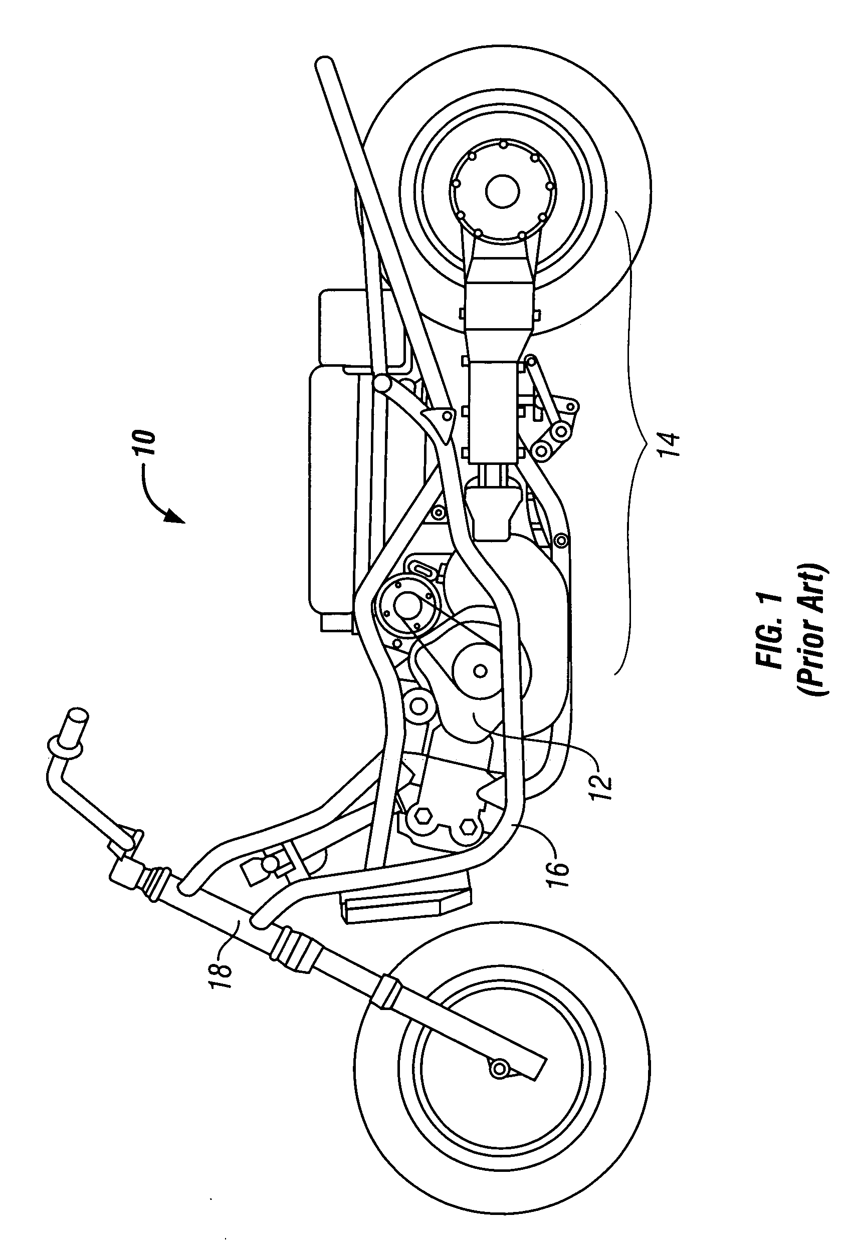
[0031]A standard motorcycle 10 commonly seen on the road today is shown in FIG. 1. As can be seen, the motorcycle 10 of current designs uses a gasoline engine 12 connected to a clutch and chain drive unit 14. The engine 12 is supported by a pair of down tubes or supporting braces 16 secured to the neck 18 of the motorcycle 10.

[0032]The present invention is generally shown in FIG. 2. A rider will sit in the seat 35 secured to a removable covering 38. As shown in FIGS. 3–5, the covering 38 and seat 35 have been removed to show the arrangement of the frame 24 and the engine carrier 26. The motorcycle 20 of the present invention generally includes a power plant 22 and fuel ta...


PUM


Abstract

A motorcycle including a frame having a backbone and engine carrier prevents the need for front support bars. The power plant is secured to the backbone and engine carrier and may be quickly removed. The power plant turns a hydraulic pump that transfers power to a hydraulic motor via hydraulic fluid. A reservoir of hydraulic fluid is preferably contained in the backbone. The hydraulic motor is contained in a swing arm and connects to one side of the rear wheel. The hydraulic motor acts as both a drive unit and a braking unit. Lights may be secured to the engine carrier to provide a better view of the road.

Description

BACKGROUND OF THE INVENTION[0001]The present invention relates generally to a motorcycle and more specifically, but without limitation, to a motorcycle having a new frame assembly and drive unit. In the past, motorcycles have typically incorporated a traditional gear drive assembly that is powered by a gasoline engine. The gasoline engine, typically having a plurality of cylinders arranged in a V formation is supported and secured to the motorcycle by a pair of bracing members extending down from the handlebar region. These supports are both unsightly and heavy. However, they have been necessary in the past to prevent flexing in the frame. It is therefore desirable to provide a motorcycle that eliminates or greatly reduces the reliance on any front bracing members.[0002]Further, because the front bracing members were an integral portion of the motorcycle frame and were required to support the engine, a larger engine would necessitate a larger frame. This affects the positioning of t...

Claims


Application Information

Patent Timeline
IPC IPC(8): B62D61/02
CPCB62M19/00B62K11/04
Inventor CARPENTER, MARK R.LINDSAY, JESS D.
Owner PARADIGM TECH
Learn More