
Filter system for spreading soot particles from a stream of exhaust gas

a filter system and exhaust gas technology, applied in the direction of exhaust treatment, filtration separation, solid separation, etc., can solve the problems of high stress on the filter material, incomplete failure of the diesel vehicle, and not only very complex discontinuous regeneration

Inactive Publication Date: 2006-05-09
FLECK CARL MARIA
View PDF17 Cites 13 Cited by
  • Summary
  • Abstract
  • Description
  • Claims
  • Application Information

AI Technical Summary

Benefits of technology

[0010]It is the object of the present invention to avoid such disadvantages and to provide a filter arrangement of the kind mentioned above in which a sufficient exhaust particulate separation is given under all conditions and even in the case of sudden load changes.
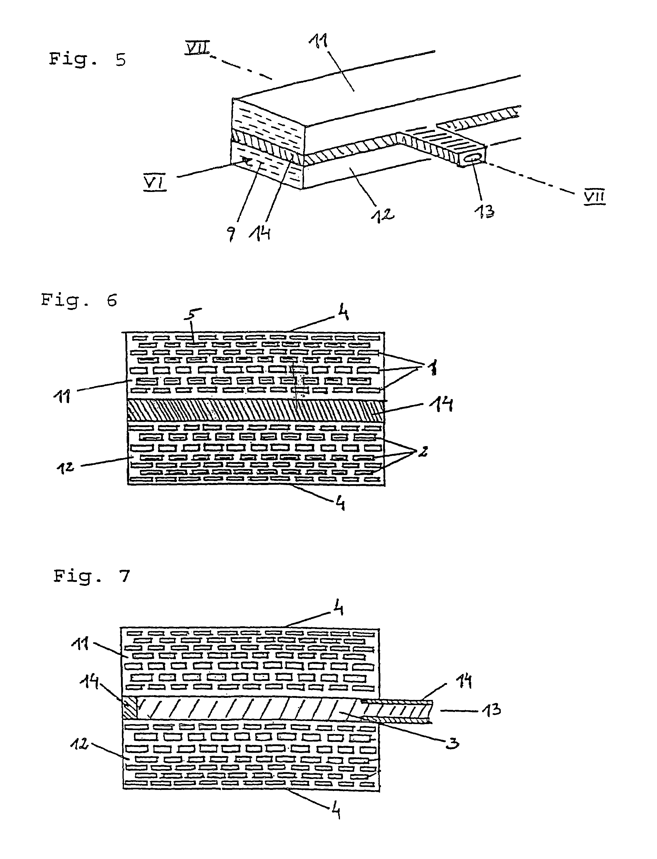
[0014]This procedure requires a high-voltage capability of the honeycomb filter, however. It is therefore decisive to correctly choose the arrangement of the alternatingly open and closed channels. Instead of the initially mentioned chessboard-like distribution of the channels which are either open or closed on their face side, it is far better if the channels which each extend at the same normal distance from the electrode are either all open or all closed on their face side. As a result of this arrangement of the closed and opened channels as provided on the inflow side of the exhaust gas it is achieved that there is no pressure difference between adjacent channels which each have the same normal distance from the electrodes and that therefore the exhaust particulates are only deposited in walls of the channels which extend substantially parallel to the electrodes, as a result of which the electric resistance of said walls decreases. These walls of mutually adjacent channels through which the actual passage of the exhaust particulates occurs each lie at the same potential, so that the decrease of the electric resistance is irrelevant, whereas the walls which extend perpendicular to the electrodes do not accumulate exhaust particulates and their electric resistance therefore remains substantially at the same level and no substantial current flow is obtained through said walls. In this way the required electrical power remains low and allows charging the honeycomb filter with pulses. The duration of the pulses and the interposed pauses can vary over a wide range.
[0024]This also leads to the advantage that the separation of the exhaust particulates can be influenced by the field pulses and it is ensured through a change of the polarity that they are separated on both separation walls of each channel which extend parallel to the electrodes and are oxidized by the produced plasma. The change of polarity can occur after each individual pulse or also after a certain number of pulses.

Problems solved by technology

In the case of an application of a direct voltage for the purpose of thermal incineration of the exhaust particulate deposits, high local temperatures occur within the entire honeycomb body, which places high stresses on the filter material.
This discontinuous regeneration is not only very complex, but may fail completely under extreme cold and thus lead to a complete failure of the diesel vehicle.
The latter requires the use of high direct voltages, which may lead to structural damage to the honeycomb filter, especially in cases when the undesirable formation of a spark occurs.

Method used


Image

  • Filter system for spreading soot particles from a stream of exhaust gas
  • Filter system for spreading soot particles from a stream of exhaust gas
  • Filter system for spreading soot particles from a stream of exhaust gas

Examples


Embodiment Construction

[0036]FIG. 1 shows the preferred embodiment of the filter in which a cylindrical geometry of the honeycomb body 6 is chosen with a centrical, axially extending bore 7. Said bore 7 is closed off on either side with a plug 8 made of isolating material. Within the hollow chamber thus produced there is an electrode 3 (not shown in FIG. 1) which is fastened to the inner side of the jacket surface of the honeycomb body and is charged via a suitable supply (not shown in FIG. 1) with high voltage. A careful sealing of the bore 7 is decisive in order to prevent the formation of conduction bridges between the electrodes 3 and 4 as a result of exhaust particulate deposits.

[0037]As is shown in FIG. 3, which shows a sectional view of the inflow side of a honeycomb body made of a porous ceramic material, channels 1, 2 are either closed off (channels 2) with plugs 5 or open (channels 1) on the inflow side, which channels are each provided with the same normal distance from the electrodes 3, 4 whic...


PUM

PropertyMeasurementUnit
Temperatureaaaaaaaaaa
Timeaaaaaaaaaa

Abstract

An apparatus for separating and converting exhaust particulates from a stream of exhaust gas, especially a diesel engine, into gaseous substances, in which the exhaust gas is guided through a honeycomb filter (6) made from a porous ceramic material whose axially extending channels (1, 2) are open merely at one face side of the filter and are closed off at the respective other face side, and a voltage is applied to electrodes (3, 4) extending parallel to the channels (1, 2) of the honeycomb filter (6). The closure of the channels (1, 2) at the face side is made in such a way that the channels (1, 2) each extending at the same normal distance from one of the electrodes (3, 4) are either all open or all closed off at their face side (9). The channels (1, 2) are mutually offset in a brickwork-like way. A sequence of voltage pulses is applied to the electrodes (3, 4) which produces electron emissions in the channels (1, 2), with pauses remaining between the individual pulses in which an electron emission is omitted.

Description

CROSS REFERENCE TO RELATED APPLICATIONS[0001]Applicant claims priority under 35 U.S.C. §119 of Austrian Application No. A 1897 / 99, filed on Nov. 10, 1999. Applicant also claims priority under 35 U.S.C. §120 of PCT / AT00 / 00294, filed on Nov. 9, 2000. The international application under PCT article 21(2) was not published in English.BACKGROUND OF THE INVENTION[0002]1. Field of the Invention[0003]The invention relates to a filter arrangement for separating and converting exhaust particulates from a stream of exhaust gas and its operation.[0004]2. Description of the Prior Art[0005]In the apparatus as known from U.S. Pat. No. 5,141,714 the exhaust particulates are separated at the pore borders of porous ceramics and incinerated from time to time by applying a voltage to the electrodes of the filter. Whereas the separation of the exhaust particulates therefore occurs substantially mechanically, the applied direct voltage is used for the thermal incineration of the deposited particulates, w...

Claims


Application Information

Patent Timeline
IPC IPC(8): B01D46/00B03C3/66B01D39/20F01N3/02B01D46/42B01D46/50B01D53/32B01J19/08B03C3/155F01N3/01F01N3/021F01N3/022F01N3/027F01N3/033F01N3/08
CPCB01D46/0063B01D46/50B01D53/323B03C3/155B03C3/66F01N3/01F01N3/0211F01N3/0222F01N3/0275F01N3/033F01N3/0892B01D46/2418Y10S55/10B01D2279/30F01N2330/06F01N2570/00F01N2570/12F01N2570/14Y10S55/30B01D46/84
Inventor FLECK, CARL MARIA
Owner FLECK CARL MARIA
Learn More