
Method, apparatus and recording medium for image processing

a technology of image processing and recording medium, applied in image enhancement, color signal processing circuit, instruments, etc., can solve the problems of skin color not giving a favorable impression, skin color looks bluish, and saturation also decreases

Active Publication Date: 2006-04-25
FUJIFILM CORP
View PDF13 Cites 15 Cited by
  • Summary
  • Abstract
  • Description
  • Claims
  • Application Information

AI Technical Summary

Benefits of technology

[0007]The present invention has been conceived based on consideration of the above problems. An object of the present invention is therefore to provide an image processing method and an image processing apparatus enabling maintenance of an impression of a specific color in an image while changing the density and / or tone thereof, and to provide a computer-readable recording medium storing a program to cause a computer to execute the image processing method.
[0016]As “the fist color space”, a color space such as an RGB color space which cannot define a specific color, but with which it is easy to change the density and the tone of the entire image by simply shifting or multiplying pixel values, can be used. As “the second color space”, a color space such as an L*a*b* color space or an L*u*v* color space enabling easy definition of a specific color and easy control of saturation and hue can be used. In the RGB color space, an amount of change per unit of digital image data is uniform in all color ranges. However, in the L*a*b* color space or in the L*u*v* color space, the amount of change per unit of digital image data is different in each color range. In other words, in one color range, a change per unit can be substantially large while the change per unit can be substantially small in another color range. Therefore, even if density change or tone change in the L*a*b* color space or in the L*u*v* color space is attempted, a degree of the change in density or tone differs between the color range having a large change per unit and the color range having a small change per unit, since the amount of change becomes different depending on the color range. As a result, when uniform change in the density or the tone is attempted in all colors, an image having been processed in this manner is ruined. For this reason, in the present invention, the density and / or the tone is changed in the first color space such as the RGB color space while the saturation and / or the hue are changed in the second color space such as the L*a*b* color space or the L*u*v* color space.
[0029]According to the present invention, the density and / or the tone are converted in the first color space. Therefore, the density and / or the tone of the color image data can be changed without ruining the image. Furthermore, for the specific color in the image, the saturation and / or the hue thereof are changed in the second color space. Therefore, the specific color can be changed to have a desired saturation and / or hue. Consequently, in a reproduced image obtained by reproduction of the processed image data, the desired density and / or tone as well as the desired saturation and / or hue, that is, the desired color impression of the specific color can be realized.

Problems solved by technology

However, although the skin color can be darkened by increasing the density, saturation also decreases and the skin color does not give a favorable impression.
Furthermore, if the density is decreased in such a manner that a tone curve for changing the tone is downwardly convex, the skin color looks bluish, also giving an impression of being unhealthy.

Method used


Image

  • Method, apparatus and recording medium for image processing
  • Method, apparatus and recording medium for image processing
  • Method, apparatus and recording medium for image processing

Examples


first embodiment

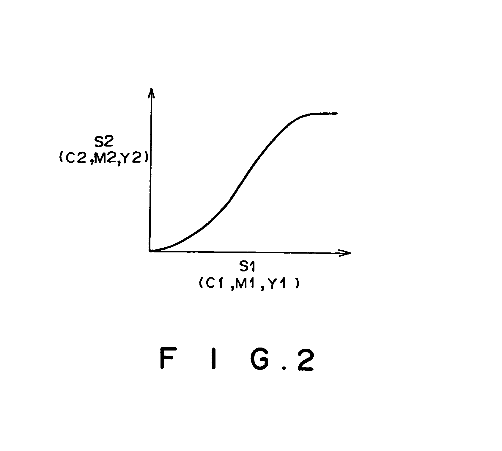
[0040]FIG. 1 is a block diagram showing an outline configuration of an image processing apparatus according to the present invention. As shown in FIG. 1, the image processing apparatus obtains processed image data S5 (R5, G5, B5) by carrying out image processing on image data S0 comprising color data R0, G0, and B0 photographed by a digital camera or read by a scanner. The image processing apparatus comprises reading means 1 for reading the image data S0 from a recording medium or for reading the image data S0 transferred via a network, logarithmic conversion means 2 for obtaining image data S1 comprising density values C1, M1 and Y1 in a CMY color space by carrying out logarithmic conversion on the image data S0, tone conversion means 3 for obtaining image data S2 by carrying out processing for converting a tone on the image data S1, density conversion means 4 for obtaining image data S3 by carrying out processing for converting density on the image data S2, inverse logarithmic con...

second embodiment

[0071]In the second embodiment, an amount of change between color impression of a skin color after the density shift by the density shifting means 14A and color impression of the skin color obtained by the subsequent tone conversion by the tone changing means 14B is found, and this amount is changed by color impression correction means 7.

[0072]In the density shifting means 14A, density values C2, M2, and Y2 of the image data S2 are shifted and the image data S2a comprising density values C2a, M2a, and Y2a are obtained. This processing is expressed by Equation (20) below in an antilogarithmic space:

R2a=αR2

G2a=αG2

B2a=αB2  (20)

where α is a coefficient determined according to how many times a DCMY key 4A is pressed down. In the case where the density is shifted downward in FIG. 3, α>1. On the other hand, α2a, G2a, and B2a are antilogarithmic values of the density values C2a, M2a and Y2a.

[0073]In the tone changing means 14B, as shown in FIG. 8, the tone is changed in such a manner that ...


PUM


Abstract

Upon conversion of density and / or tone of an image, an impression of a specific color in the image is also corrected. Tone conversion is carried out in a CMY color space on image data having been subjected to logarithmic conversion, and density conversion processing is also carried out thereon in density conversion means. The image data are then subjected to inverse logarithmic conversion. In LCH conversion means, the image data are converted into lightness, saturation and hue, and the saturation and / or the hue are corrected by color impression correction means. By converting the data into RGB data by using RGB conversion means, processed image data are obtained.

Description

BACKGROUND OF THE INVENTION[0001]1. Field of the Invention[0002]The present invention relates to a method and an apparatus for carrying out image processing for changing density and tone of digital color image data obtained by a digital camera or a scanner. The present invention also relates to a computer-readable recording medium storing a program to cause a computer to execute the image processing method.[0003]2. Description of the Related Art[0004]Image processing systems for reproducing digital image data obtained by digital still cameras (hereinafter called digital camera) and digital image data obtained by reading images recorded on films as hard copies such as prints or as soft copies on display screens have been proposed. In such an image processing system, digital image data are also provided by being recorded in a recording medium such as a CD-R. In the case where such an image obtained by a digital camera or a scanner is printed, the image is expected to have as high a qu...

Claims


Application Information

Patent Timeline
IPC IPC(8): G06F15/00G06T5/00G06T11/00H04N1/46H04N1/60H04N9/64
CPCG06T11/001
Inventor TAKEMOTO, FUMITO
Owner FUJIFILM CORP
Learn More