
Floor resurfacing disks for rotary floor resurfacing machines

a technology of rotary floor resurfacing and floor resurfacing disk, which is applied in the direction of metal-working equipment, portable grinding machines, grinding heads, etc., can solve the problems of uneven surface of exposed floor surface with remaining floor covering, poor adhesion to hardened adhesive, and often resurfacing of painted concrete floors. achieve the effect of improving the conformance to the floor surfa

Inactive Publication Date: 2006-04-25
LITE PREP SURFACE PREPARATION EQUIP
View PDF30 Cites 48 Cited by
  • Summary
  • Abstract
  • Description
  • Claims
  • Application Information

AI Technical Summary

Benefits of technology

"The invention is a resurfacing disk for removing material from a floor surface. It includes a rigid upper disk with resilient connectors mounted on it to pivot, allowing the floor resurfacing devices to conform to the floor surface. The resilient connectors are individually replaceable for easy replacement. The resurfacing disk is designed to be easily mounted on a conventional rotary floor resurfacing machine and includes a sanding disk or a rotary cutter for removing material from the floor surface. The technical effects of the invention include improved conformance to the floor surface, easy replacement of the resilient connectors, and efficient use on industrial refinishing machines."

Problems solved by technology

For example, painted concrete floors are often resurfaced after the existing paint becomes chipped and the floor surface becomes pitted.
Carpeting, linoleum tiles, and other floor coverings are often originally secured to the floor using an adhesive to prevent movement, but these floor coverings become worn, loose, or cracked over time.
When these floor coverings are taken for replacement such as by using hand scrapers and other tools, the exposed floor surface with remaining floor covering and hardened adhesive is typically very rough.
While these grinding machines are convenient to transport to the site where the floor to be resurfaced is located, they cover only a small surface area with each pass along the floor surface and thus require considerable time to grind or sand even small areas of the floor.
While the larger wheeled resurfacing machines such as the multi-disk floor grinding machine of Duncan, et al. are easier to operate and cover more surface area per pass than the hand-held grinders, the resurfacing disks do not pivot adequately to allow the grinding pads to closely conform to the floor surface.
While this arrangement is better than having a rigid connection between the disk mounts and the resurfacing disks, the resilient connector are prone to wear out overtime and are not readily replaceable.
While these resurfacing disks and mounting arrangements may provide some degree of resiliency between the rotary disk mounts and the floor resurfacing devices, most are relatively complicated in design and are not built rugged enough for continuous use on industrial floor resurfacing machines.

Method used


Image

  • Floor resurfacing disks for rotary floor resurfacing machines
  • Floor resurfacing disks for rotary floor resurfacing machines
  • Floor resurfacing disks for rotary floor resurfacing machines

Examples


first embodiment

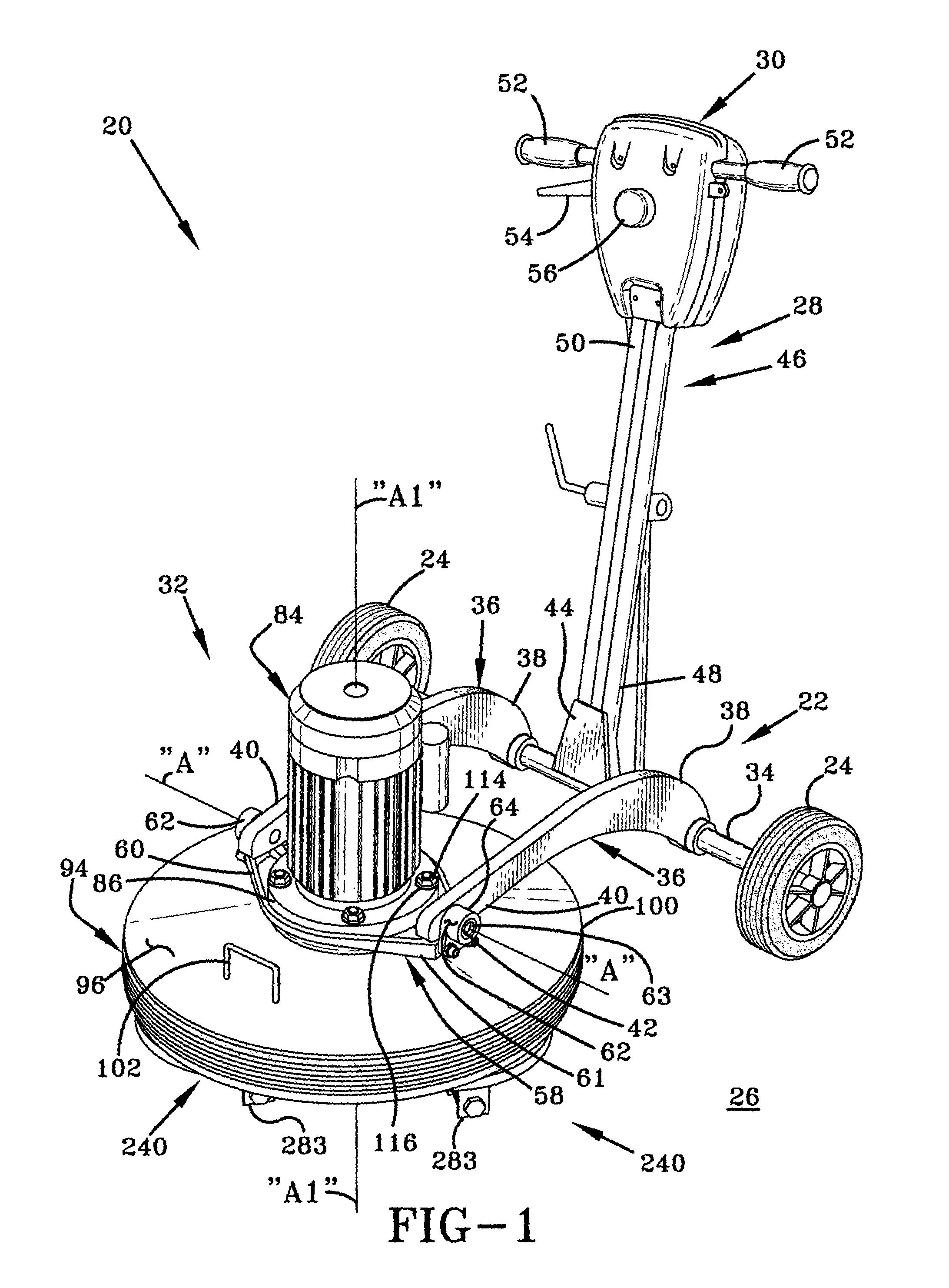
[0043]In accordance with the invention, the resurfacing disk of the present invention is shown in FIGS. 3–6, and is indicated generally at 240, which is provided for each disk mount 167. The resurfacing device 240 is removably mountable to each disk mount 167 using a plurality of the mounting pins 202, typically four for each disk mount 167, in a spaced relationship for rotation therewith about respective of the resurfacing device axes “A2” and about the main axis “A1”. Each resurfacing device 240 includes a substantially rigid upper disk 242 having respective upper and lower surfaces 244 and 246, a resilient replaceable grommet 248 for each mounting pin 202, a retaining device comprising a retaining plate 249 of circular shape, and at least one resurfacing device 255 removably mounted to the lower surface 246 of the upper disk 242 depending downwardly therefrom adapted for removing the material from the floor surface 26 as said resurfacing devices 240 move thereon. The upper disk 2...

second embodiment

[0048]the resurfacing disk of the present invention is indicated at 312 in FIGS. 7–9, which is provided for each disk mount 167. The resurfacing device 312 is removably mountable to each disk mount 167 using a plurality of the mounting pins 202, typically four for each disk mount 167, in a spaced relationship for rotation therewith about respective of the resurfacing device axes “A2” and about the main axis “A1”. Each resurfacing device 312 includes the substantially rigid upper disk 242 having the respective upper and lower surfaces 244 and 246, the resilient replaceable grommets 248 for each mounting pin 202, the retaining plate 249, a resiliently deformable lower disk 314, which is made of semi-rigid hard sponge material having an upper surface 316 adhesively or otherwise mounted to the lower surface 246 of the upper disk 242 and a lower surface 318, and at least one floor resurfacing device 320 removably mounted to the lower surface 318 of the lower disk 314 depending downwardly...


PUM


Abstract

A resurfacing disk which mounts to a rotatable disk mount of a conventional rotary floor resurfacing machine. The resurfacing disk includes a rigid upper disk with four counterbored holes through an upper surface corresponding to four downwardly open holes of each disk mount. A resilient, flanged grommet is retained extending through corresponding holes of a retaining plate mounted to the upper surface. The grommets include respective vertically oriented longitudinal bores closely receive a mounting pin which extends from a corresponding hole of the disk mount. A plurality of rotary cutters each include a bracket which mounts to the upper disk opposite the grommets and an externally toothed cutter rotatably mounted thereto. The rotatable toothed cutters are oriented radially outwardly of the resurfacing disk so as to rotate while engaging the floor as the resurfacing disk spins with the disk mount. A resiliently deformable lower disk may be mounted in place of the rotary cutters and a sandpaper disk is removably affixed thereto using sheets interconnectable hook and a loop fastener material. The grommets and the lower disk deform to permit the floor resurfacing device to more closely follow contours of the floor surface and are easily replaceable if damaged or worn out.

Description

BACKGROUND OF THE INVENTION[0001]1. Technical Field[0002]Generally, the invention relates to a rotary floor prepping device. More particularly, the invention relates to a rotary floor prepping device which includes a substantially rigid upper disk with a resilient connector affixed at an upper surface thereof. A plurality of pins are used to removably mount the connector and upper disk to the rotary disk mount. One or more floor surfacing devices mount to the upper disk depending downwardly therefrom for prepping the floor surface. Specifically, the invention relates to a rotary resurfacing disk for removing material from a floor surface having a substantially rigid upper disk with a plurality of resilient, replaceable grommets affixed at an upper surface thereof. A plurality of pins are used to removably mount the grommets and upper disk to the rotary disk mount. One or more floor surfacing devices mount to the upper disk or to a resilient lower disk mounted below the upper disk de...

Claims


Application Information

Patent Timeline
Patent Type & Authority Patents(United States)
IPC IPC(8): B24B23/00B24B7/18B24B41/047
CPCB24B41/047B24B7/186
Inventor JORDAN, TODD A.
Owner LITE PREP SURFACE PREPARATION EQUIP
Learn More