Supercharge Your Innovation With Domain-Expert AI Agents!

Circuit and method for generating a local clock signal synchronized to an externally generated reference clock signal

a local clock signal and reference clock technology, applied in the direction of generating/distributing signals, digital transmission, instruments, etc., can solve the problems of design which loses locks, dq line drivers with significant delays, etc., to achieve the effect of increasing the available range of locks, and reducing the size of the layou

Inactive Publication Date: 2006-04-11
WALLER WILLIAM KENNETH
View PDF7 Cites 19 Cited by
  • Summary
  • Abstract
  • Description
  • Claims
  • Application Information

AI Technical Summary

Benefits of technology

[0023]Each delay line has separate delay controls including a counter that sets the number of incremental delays applied by the delay line to the clock signal. When the delay of a delay line is adjusted, the counter of the next, higher resolution delay line is typically set at midrange, to maximize its available range of locking.
[0025]The coarse delays also permit the DLL to operate over the required frequency range using far fewer delay elements than designs having a only single delay line, giving the advantages of smaller layout and lower power consumption compared to prior art.
[0036](g) All-digital controls for rapid convergence and stable, robust operation over full range of temperature and manufacturing process conditions,

Problems solved by technology

The fact that the frequency of the reference clock is not known precisely presents an obstacle to meeting the above requirement.
The fact that the DQ line drivers have significant delays presents another obstacle.
A design which loses lock due to a change in supply voltage or temperature cannot function until lock is regained.
This approach has the disadvantage of requiring many delay stages to do its job.
Implementing such a large number of stages requires more device size and power consumption than necessary.
The large number of stages also causes the disadvantage of slow locking.
The phase detector must wait at least two clock cycles before making each decision, and each decision can only adjust total delay by a single unit delay.
The design of FIG. 1 has the further disadvantage of making delay adjustments by varying the location where the clock signal enters the delay line, so the adjustments propagate through all active delay elements before evaluation at the phase detector.
Adjusting at the beginning end, rather than the trailing end, of the delay line slows evaluation of the adjustment, because the design has to wait before evaluating until each adjustment propagates to the phase detector.
The FIG. 1 design has a further disadvantage of requiring flip-flops in the shift register outputs that control the delay line.
The use of flip-flops causes the device to suffer extra size or reduced performance.
The Kuge patent has the disadvantage of using analog voltage controls for initial steps toward lock, causing speed of locking to be less than optimal.
The Kuge patent has the further disadvantage of having variable size delay steps in its delay line, while the delay steps in its delay buffer are a fixed size.
This problem will cause the DLL to have a variable locking resolution.
The total delay will not change in a uniform manner as the counter is incremented and decremented.
Temperature variations cause changes in circuit delay, requiring the DLL to make small delay adjustments after the initial lock.

Method used


Image

  • Circuit and method for generating a local clock signal synchronized to an externally generated reference clock signal
  • Circuit and method for generating a local clock signal synchronized to an externally generated reference clock signal
  • Circuit and method for generating a local clock signal synchronized to an externally generated reference clock signal

Examples


Embodiment Construction

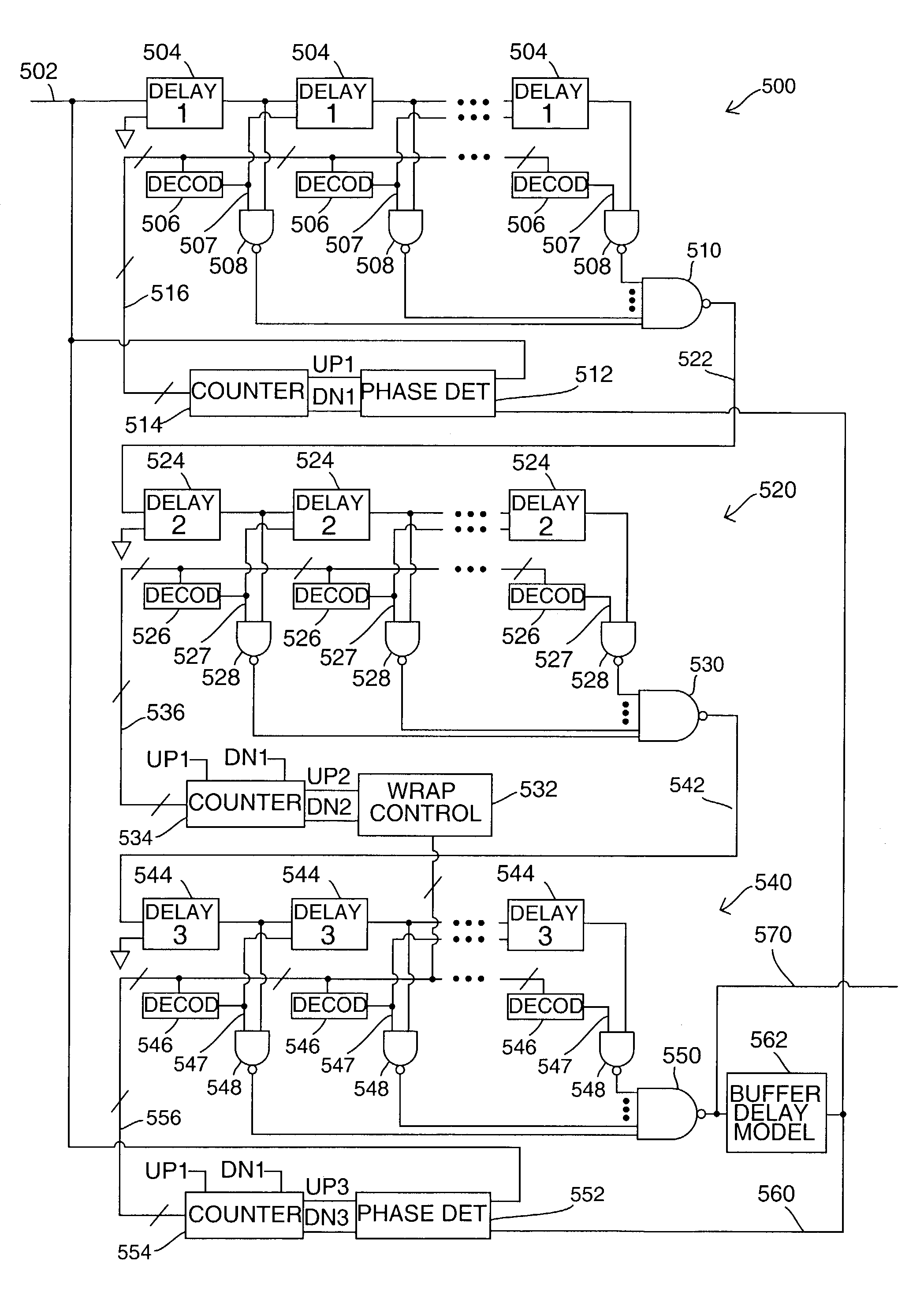
[0047]In FIG. 3, a buffered reference clock 302 is the input signal. For brevity, FIG. 3 does not show the reference clock input buffer. Buffered reference clock 302 connects to a first delay element in first delay line 300, to a first input of phase detector 312 in delay line 300, and to a first input of phase detector 332 in delay line 320. DQ clock 350 is the output signal from the DLL. DQ clock is driven by delay line 320, and connects further to buffer delay model 342. A replica clock signal 340, driven by the buffer delay model, is the feedback control signal for the loop. The replica clock connects to a second input of phase detector 312, and to a second input of phase detector 332.

[0048]In FIG. 3 delay line 300, the clock signal passes through delay elements 304 in series. Each delay element has an input node for receiving a clock signal, and an output node for conveying a copy of the clock signal delayed by a first delay time. The input node of each delay element in the del...


PUM


Abstract

A delay locked loop for generating a replica clock signal synchronized to an externally generated clock signal comprises a succession of separately controlled delay lines. Each of the delay lines has different delay resolution.

Description

CROSS-REFERENCE TO RELATED APPLICATIONS[0001]Not ApplicableSTATEMENT REGARDING FEDERALLY SPONSORED RESEARCH OR DEVELOPMENT[0002]Not ApplicableREFERENCE TO SEQUENCE LISTING, A TABLE, OR A COMPUTER PROGRAM LISTING COMPACT DISK APPENDIX[0003]Not ApplicableBACKGROUND OF THE INVENTION[0004]This invention relates to the field of semiconductor integrated circuits, particularly to circuits useful for generating local clock signals synchronized to an external reference clock, and to semiconductor memory devices with such circuits.[0005]System specifications for double data rate dynamic random access memory(DDR DRAM) require the device in a read cycle to switch its data lines(DQ) coincident with transitions of an externally generated reference clock. The fact that the frequency of the reference clock is not known precisely presents an obstacle to meeting the above requirement. The fact that the DQ line drivers have significant delays presents another obstacle.[0006]To meet the above requireme...

Claims


Application Information

Patent Timeline
IPC IPC(8): G06F1/12H03L7/06
CPCG06F1/12
Inventor WALLER, WILLIAM KENNETH
Owner WALLER WILLIAM KENNETH
Features
  • R&D
  • Intellectual Property
  • Life Sciences
  • Materials
  • Tech Scout
  • Unparalleled Data Quality
  • Higher Quality Content
  • 60% Fewer Hallucinations
Learn More