
Linear motion apparatus and method for manufacturing thereof

a technology of motion apparatus and manufacturing method, which is applied in the direction of manufacturing tools, hoisting equipment, gearing, etc., can solve the problems of high difficulty, complicated setting of working machine, and inability to properly operate ball screw operation, so as to increase the working cost of the working machine.

Inactive Publication Date: 2006-04-11
NSK LTD
View PDF8 Cites 4 Cited by
  • Summary
  • Abstract
  • Description
  • Claims
  • Application Information

AI Technical Summary

Benefits of technology

[0008]The present invention aims at eliminating the drawbacks found in the conventional ball screws. Accordingly, it is an object of the present invention to provide a linear motion apparatus which can prevent the occurrence of the ball clogging phenomenon in the boundary portion between the rolling element rolling passage and rolling element return passage without incurring an increase in the manufacturing cost thereof.
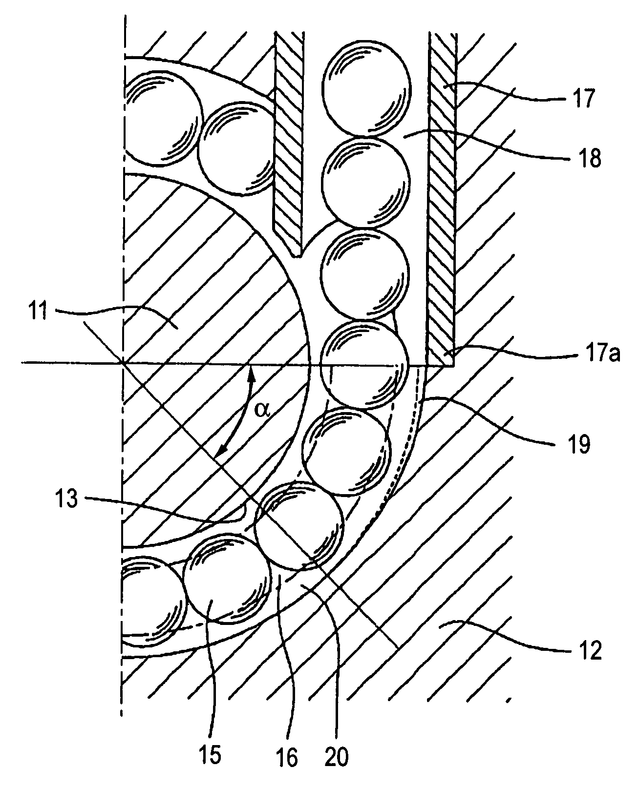
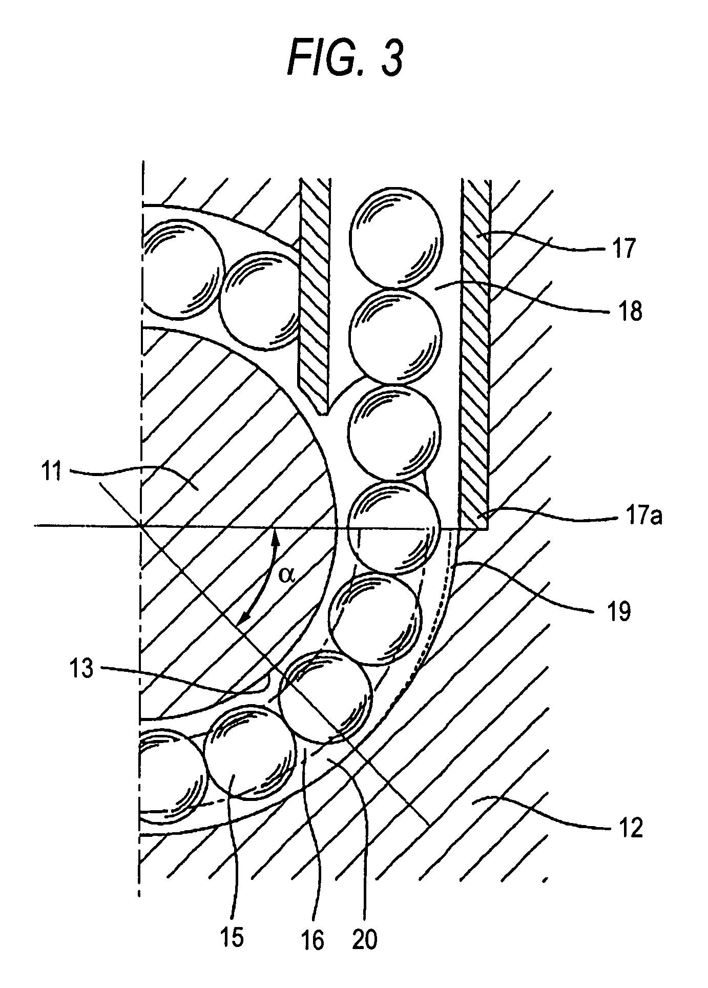
[0011]According to the present structure, the escape portion with its grinding depth increasing gradually toward the open end of the rolling element return passage can be formed in the rolling element rolling groove of the movable body without using a working machine such as an NC grinding machine, thereby being able to prevent the occurrence of a ball clogging phenomenon in the boundary portion between the rolling element rolling passage and rolling element return passage without incurring an increase in the working cost thereof. Also, since the grinding depth of the escape portion to be formed in the rolling element rolling groove of the movable body is varied gradually to thereby be able to eliminate the need to set the working amount of a working machine according to the working positions thereof, the escape portion can be formed in the rolling element rolling groove of the movable body without increasing the working cost thereof. Further, in case where there is employed a working operation to reciprocate visco-elastic media mixed with abrasives through a rolling element circulation passage, not only in the end portions of the rolling grooves but also in the stepped portion of the circulation passage which is believed to interfere the rolling movements of the reciprocating rolling elements, it is possible to enforce an R forming operation which can prevent the rolling elements from being caught by the stepped portion.

Problems solved by technology

However, in case where the ball return member is formed by a tubular-shaped member having an inside diameter about 1.1 to 1.2 times the diameter of the ball, there is produced a stepped portion in the boundary portion between the ball return passage and ball rolling passage, which causes a ball clogging phenomenon that the balls moving from the ball return passage into the ball rolling passage are caught by the stepped portion, thereby raising a possibility that the proper operation of the ball screw can be greatly impeded.
However, in this structure, there is still found the following problem.
That is, when such escape portion as disclosed in the above-cited publication is going to be formed in the ball rolling groove of the nut using a working machine such as a ball end mill, the setting of the working machine is very complicated and thus provides a high degree of difficulty, which results in an increase in the manufacturing cost of the ball screw.

Method used


Image

  • Linear motion apparatus and method for manufacturing thereof
  • Linear motion apparatus and method for manufacturing thereof
  • Linear motion apparatus and method for manufacturing thereof

Examples


Embodiment Construction

[0019]Now, description will be given below of a ball screw according to an embodiment of the present invention with reference to the accompanying drawings.

[0020]FIGS. 1 to 3 show an embodiment in which the present invention is applied to a ball screw. Specifically, FIG. 1 is a section view of a ball screw according to the embodiment of the present invention, taken along the axial direction of the ball screw, and FIG. 2 is a section view of the ball screw according to the present embodiment, taken along the diameter direction thereof. As shown in FIGS. 1 and 2, the ball screw 10 includes a screw shaft 11 serving as a guide shaft and a nut 12 serving as a movable body which can be movably fitted with the outer periphery of the screw shaft 11; and, in the outer peripheral surface of the screw shaft 11, there is formed a spiral-shaped ball rolling groove 13. This ball rolling groove 13 is disposed opposed to a spiral-shaped ball rolling groove 14 which is formed in the inner peripheral ...


PUM

PropertyMeasurementUnit
depthaaaaaaaaaa
shapeaaaaaaaaaa
diameteraaaaaaaaaa

Abstract

A linear motion apparatus has a guide shaft including a spiral-shaped or linear-shaped rolling element rolling groove, a movable body including a spiral-shaped or linear-shaped rolling element rolling groove opposed to the rolling element rolling groove of the guide shaft, a large number of rolling elements rollably moving along a rolling element rolling passage formed between the rolling element rolling grooves of the guide shaft and movable body and, a rolling element return passage communicating with the rolling element rolling passage, wherein, in the portion of the rolling element rolling groove of the movable body that is adjacent to an open end of a rolling element return passage, an escape portion is formed by abrasive flow machining in such a manner that the grinding depth thereof increases gradually toward the open end of the rolling element return passage.

Description

BACKGROUND OF THE INVENTION[0001]1. Field of the Invention[0002]The present invention relates to a linear motion apparatus of a circulation type such as a ball screw, a linear guide and a ball spline and so on.[0003]2. Description of the Related Art[0004]In a machine tool and an injection molding machine, as a mechanism part thereof for converting the rotational movement of a motor or the like into a linear movement, there is used a ball screw. A ball screw of this type includes a screw shaft and a nut to be movably fitted with the outer periphery of the screw shaft. In case where one of the screw shaft and nut is rotated, a large number of balls incorporated into the nut are allowed to roll between two spiral-shaped ball rolling grooves which are respectively formed in the outer peripheral surface of the screw shaft and in the inner peripheral surface of the nut in such a manner that they are opposed to each other. And, the ball screw of this type further includes a ball return mem...

Claims


Application Information

Patent Timeline
Patent Type & Authority Patents(United States)
IPC IPC(8): F16H25/22B23Q5/40B23Q1/26B24B15/00B24B31/116F16C29/06F16H25/24
CPCB23Q5/406B24B15/00F16H25/2214B24B31/116Y10T74/19767Y10T74/19749
Inventor KAJITA, TOSHIHARU
Owner NSK LTD
Learn More