
Hydrodynamic slip ring

a technology of slip rings and hydrodynamics, applied in the field of brushes, can solve the problems of graphite brushes wearing out from both electrical wear and mechanical wear, protection film shift wear from the ring, electrical wear and other problems, to achieve the effect of reducing the number of brushes

Inactive Publication Date: 2006-03-28
PRATT & WHITNEY POWER SYST
View PDF7 Cites 16 Cited by
  • Summary
  • Abstract
  • Description
  • Claims
  • Application Information

AI Technical Summary

Benefits of technology

[0006]In accordance with the present invention there is provided a slip ring assembly for transferring electrical current to an electrical device such as a rotating machine. The slip ring assembly has a housing that is attachable to the electrical device. Disposed within the housing is a rotatable slip ring and a flexible conductor. The flexible conductor is configured to conform to the shape of the slip ring and conduct an electric current. A fluid is contained within the housing. The fluid forms a conductive film between the slip ring and the conductor when the slip ring rotates through hydrodynamic forces. The conductive film is operative to transfer electrical current between the slip ring and the conductor while also preventing wear of the slip ring and flexible conductor.
[0010]In accordance with the present invention, there is provided a method of conducting electrical current between a power source and an electrical device with the slip ring assembly. The method comprises rotating the slip ring within the housing to form a conductive film with fluid between the flexible conductor and the slip ring. Next, electrical current is transferred between the flexible conductor and the slip ring. The conductive film formed by the fluid prevents wear to the slip ring and flexible conductor.

Problems solved by technology

The protective film shifts wear from the ring to the brush which is easily replaced during routine machine maintenance.
The graphite brushes wear out from both electrical wear and mechanical wear.
The electrical wear results from the vaporization of the graphite at scattered contact points of the ring that randomly move across the interface surface.
Mechanical wear results from the dry mechanical friction between the graphite and the surface of the metallic ring.
However, these brushes cannot handle the high current density required for industrial applications.

Method used


Image

  • Hydrodynamic slip ring
  • Hydrodynamic slip ring
  • Hydrodynamic slip ring

Examples


Embodiment Construction

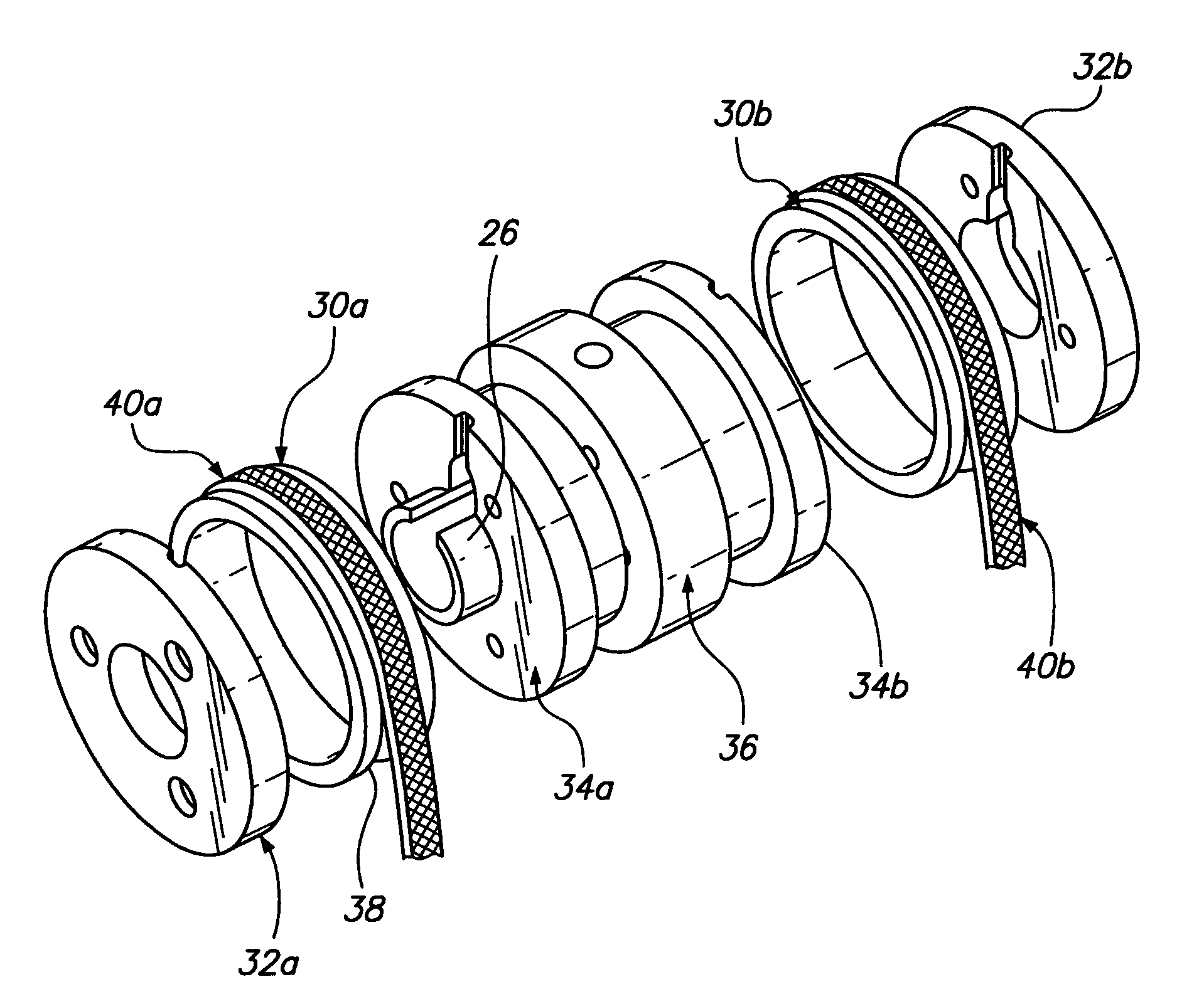
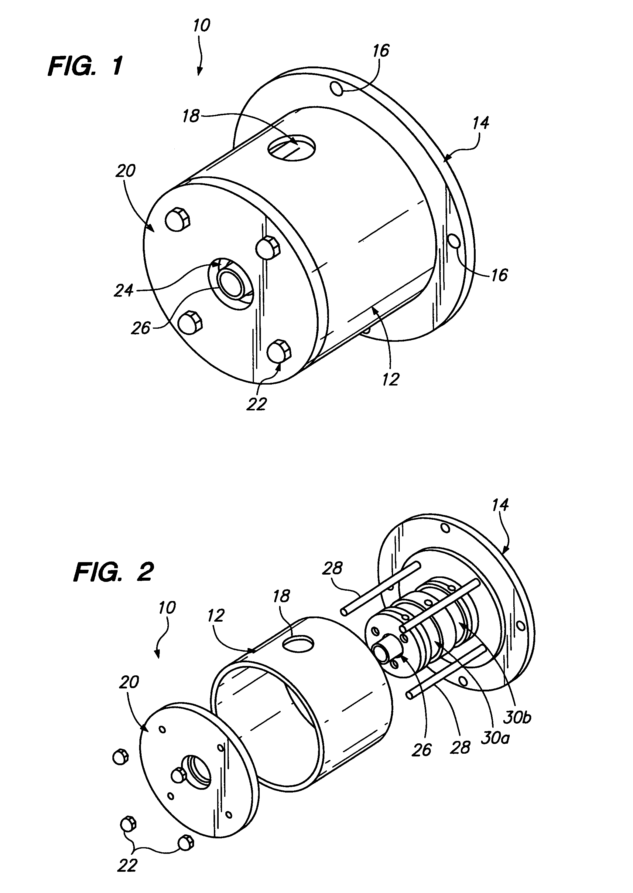
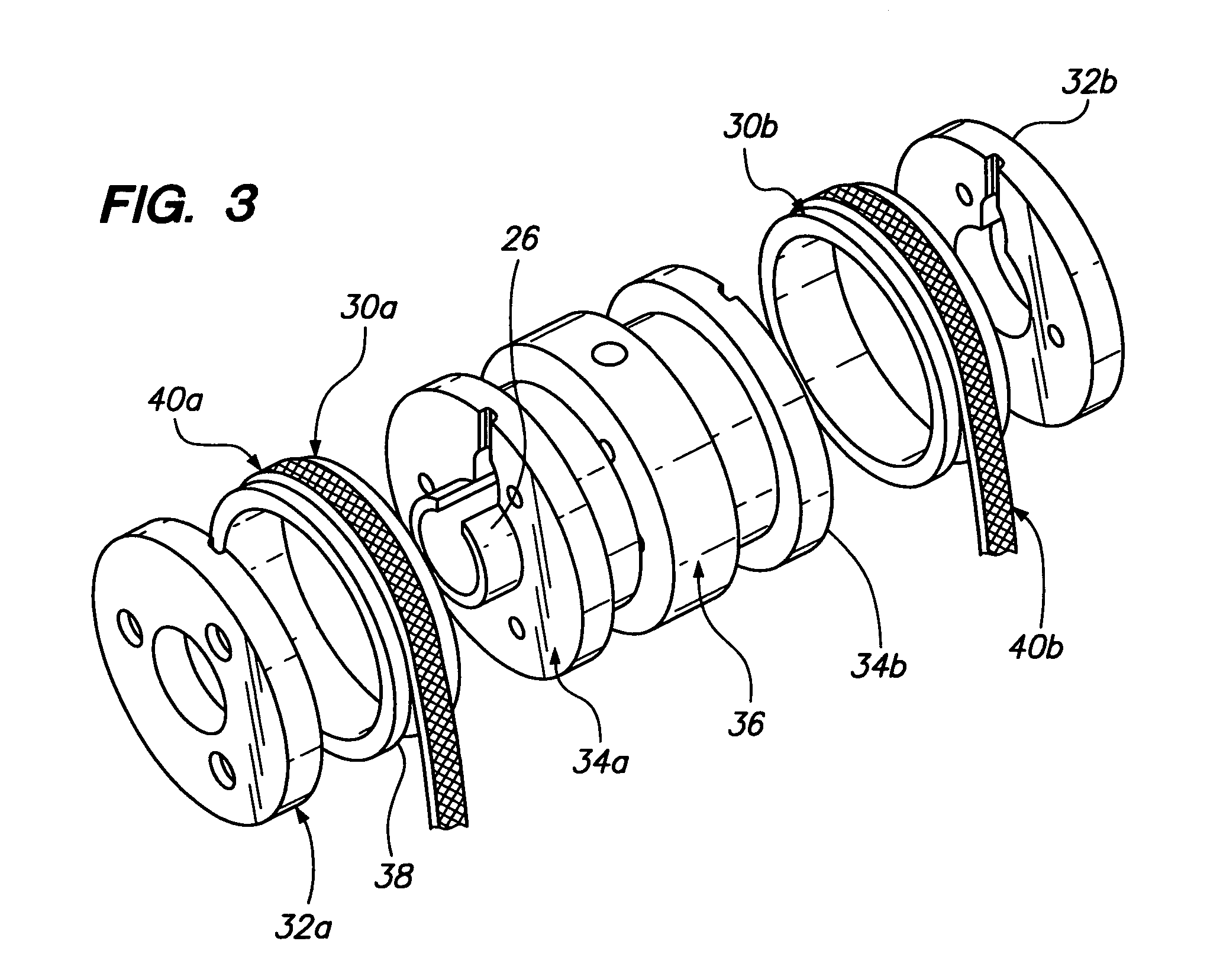
[0015]Referring now to the drawings wherein the showings are for purposes of illustrating preferred embodiments of the present invention only, and not for purposes of limiting the same, FIG. 1 is a perspective view of a hydrodynamic slip ring assembly 10. The slip ring assembly 10 is used to transfer electrical energy between a power source and an electrical machine. The slip ring assembly 10 is a self-contained unit and is adapted to be mounted onto a shaft of an electric motor. The slip ring assembly 10 has a housing 12 with a mounting flange 14 that is adapted to be attached to the electric motor. The mounting flange 14 can be formed integral with the housing 12 or be a separate piece attached thereto. The mounting flange 14 has a series of apertures 16 for inserting a mounting bolt of the motor therethrough. The housing 12 is generally cylindrical and has a liquid fill port 18 formed therein for filling the housing 12 with a fluid. The fill port 18 may be capped with an appropri...


PUM


Abstract

A slip ring assembly for transferring electrical current to an electrical device is disclosed. The slip ring assembly has a housing that is attachable to the electrical device. Disposed within the housing is a rotatable slip ring and a flexible conductor. The flexible conductor is configured to conform to the shape of the slip ring and conduct an electric current. A fluid is contained within the housing. The fluid forms a conductive film between the slip ring and the conductor when the slip ring rotates through hydrodynamic forces. The conductive film is operative to transfer electrical current between the slip ring and the conductor while also preventing wear of the slip ring and conductor.

Description

FIELD OF THE INVENTION[0001]The present invention generally relates to brushes for an electric motor and more particularly to a slip-ring submerged in an liquid medium in order to decrease wear of the brushes, and, increase current density and heat removal.BACKGROUND OF THE INVENTION[0002]Filamentary metal brushes have been used to transfer electrical energy from a power source to the rotating member of a machine. The brushes comprise a plurality of fine hair-like metallic fibers that are individually suspended independent of the surrounding fibers. Each of the fibers provides a discrete contact point with a metallic ring surface of the rotating member of the electrical machine. Accordingly, numerous contact points are established and act in concert to conduct electrical current between the brushes and the rotating member of the electrical machine.[0003]As the amount of current has increased in electrical machines, the format of the brushes has changed. In order to handle large amou...

Claims


Application Information

Patent Timeline
IPC IPC(8): H01R39/08
CPCH01R39/646H01R39/30
Inventor KERLIN, JACK H.
Owner PRATT & WHITNEY POWER SYST
Learn More