
Integrated circuit devices having duty cycle correction circuits that receive control signals over first and second separate paths and methods of operating the same

Inactive Publication Date: 2006-03-21
SAMSUNG ELECTRONICS CO LTD
View PDF8 Cites 86 Cited by
  • Summary
  • Abstract
  • Description
  • Claims
  • Application Information

AI Technical Summary

Benefits of technology

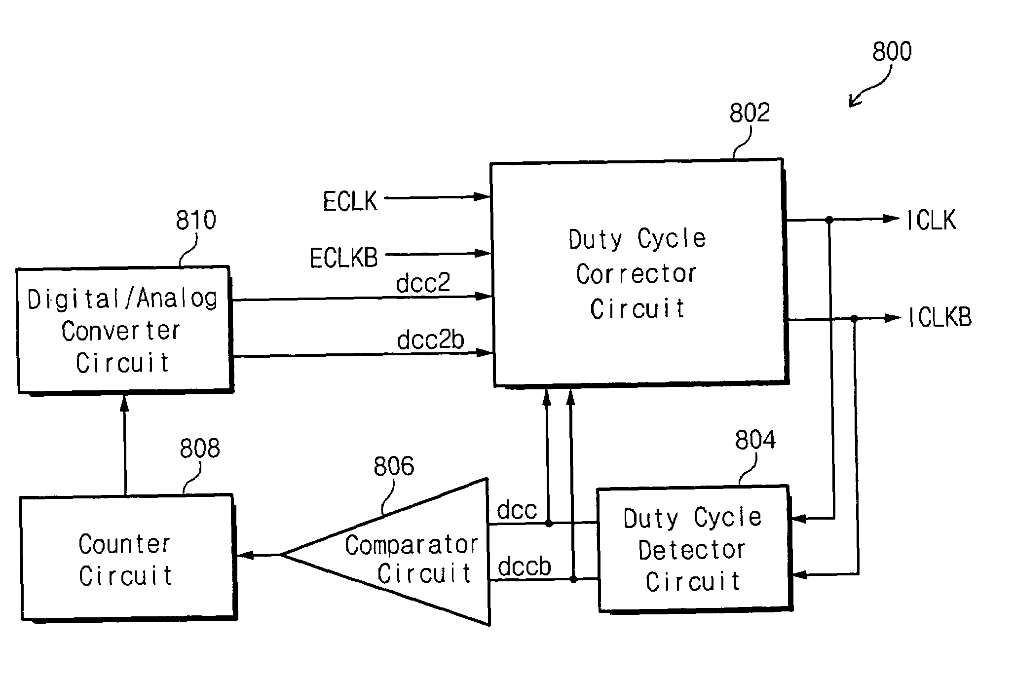
[0016]Embodiments of the present invention provide digital duty cycle correction circuits including a duty cycle detector circuit configured to generate first and second control values associated with a first internal clock signal and a second internal clock signal, respectively. A comparator circuit is also provided and is configured to compare the first control value to the second control value and provide a comparison result. A counter circuit is configured to perform an addition and/or a subtraction operation responsive to the comparison result to provide a digital c

Problems solved by technology

However, increasing demand for improved systems may require DRAMs that can process even more data at even higher speeds.
There are limitations on the amount of data that may be input to and / or output from a memory device per cycle of a system clock.
Thus, when a clock signal having a duty cycle that is greater than or less than 50% is provided as an input, the device may not perform very well.
However, external clocks input into integrated circuit memory devices are typically asymmetric, i.e., the duty cycle is not 50% and may be further distorted by characteristics of the integrated circuit memory device.
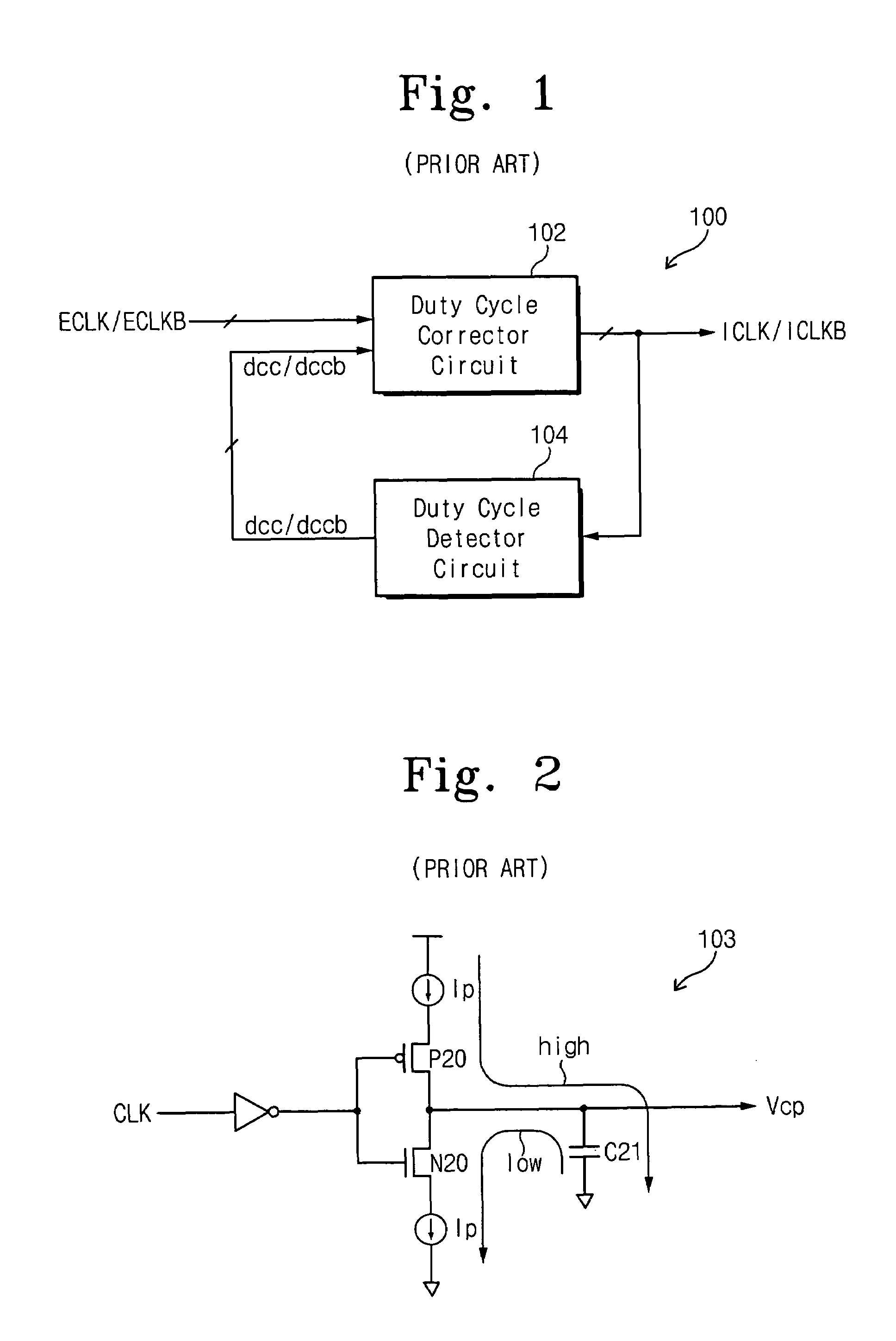
However, the analog duty cycle correction circuit may experience a time delay while the capacitors of the charge pumps are recharged after power is supplied to the integrated circuit memory device.
The increase in size may be a problem as the size of integrated circuit devices continue to decrease.

Method used


Image

  • Integrated circuit devices having duty cycle correction circuits that receive control signals over first and second separate paths and methods of operating the same
  • Integrated circuit devices having duty cycle correction circuits that receive control signals over first and second separate paths and methods of operating the same
  • Integrated circuit devices having duty cycle correction circuits that receive control signals over first and second separate paths and methods of operating the same

Examples


Embodiment Construction

[0033]The present invention now will be described more fully hereinafter with reference to the accompanying drawings, in which preferred embodiments of the invention are shown. This invention may, however, be embodied in many different forms and should not be construed as limited to the embodiments set forth herein; rather, these embodiments are provided so that this disclosure will be thorough and complete, and will fully convey the scope of the invention to those skilled in the art. It will be understood that when an element is referred to as being “coupled” or “connected” to another element, it can be directly coupled to or connected to the other element or intervening elements may also be present. It will be further understood that when an element is referred to as being “directly coupled” or “directly connected” to another element, no intervening elements may be present. Like numbers refer to like elements throughout.

[0034]It will be understood that although the terms first and...


PUM


Abstract

Digital duty cycle correction circuits are provided including a duty cycle detector circuit configured to generate first and second control values associated with a first internal clock signal and a second internal clock signal, respectively. A comparator circuit is also provided and is configured to compare the first control value to the second control value and provide a comparison result. A counter circuit is configured to perform an addition and / or a subtraction operation responsive to the comparison result to provide a digital code. A digital to analog converter is configured to generate third and fourth control values responsive to the digital code. Finally, a duty cycle corrector circuit is configured to receive first and second external clock signals and the first through fourth control values and generate the first and second internal clock signals having a corrected duty cycle. The first and second control values are received over a first path and the third and fourth control values are received over a second path, different from the first path. Related methods of operating duty cycle correction circuits are also provided.

Description

RELATED APPLICATION[0001]This application is related to and claims priority from Korean Patent Application No. 2003-19653 filed on Mar. 28, 2003, the disclosure of which is hereby incorporated herein by reference as if set forth in its entirety.FIELD OF THE INVENTION[0002]The present invention relates to integrated circuit devices and methods of operating the same and, more particularly, to integrated circuit devices having duty cycle correction circuits and methods of operating the same.BACKGROUND OF THE INVENTION[0003]Recently, the speed of integrated circuit memory devices, for example, dynamic random access memories (DRAMs), has increased to improve the performance of existing systems. However, increasing demand for improved systems may require DRAMs that can process even more data at even higher speeds. Accordingly, synchronous dynamic random access memories (SDRAMs) that operate in synchronization with system clocks have been developed for high-speed operation, thus significan...

Claims


Application Information

Patent Timeline
IPC IPC(8): H03K3/017G11C29/00G11C8/00H03K5/156H03L7/00
CPCH03K5/1565G11C8/00
Inventor LEEKIM, KYU-HYOUN
Owner SAMSUNG ELECTRONICS CO LTD
Learn More