
Circuit devices, circuit devices which include light emitting diodes, assemblies which include such circuit devices, flashlights which include such assemblies, and methods for directly replacing flashlight bulbs

a technology of circuit devices and light-emitting diodes, which is applied in the direction of lighting and heating apparatus, process and machine control, instruments, etc., can solve the problems of the circuitry of the zxsc310 device that cannot operate in buck mode, and achieve the effects of enhancing the longevity of the electrical component(s), increasing the percentage of useful power, and increasing storage energy

Active Publication Date: 2006-03-21
LEDDYNAMICS
View PDF4 Cites 110 Cited by
  • Summary
  • Abstract
  • Description
  • Claims
  • Application Information

AI Technical Summary

Benefits of technology

[0011]The present invention provides a circuit device for driving one or more electrical components (e.g., one or more LEDs), which overcomes the drawback described above. In addition, the present invention provides a circuit device for driving one or more electrical components (e.g., one or more LEDs), which circuit device significantly increases the percentage of useful power from a power source being delivered to the electrical component(s), relative to conventional circuit devices. The present invention further provides a circuit device for driving one or more electrical components (e.g., one or more LEDs) which enhances the longevity of the electrical component(s). The present invention further provides a circuit device for driving one or more electrical components (e.g., one or more LEDs) which compensates in the event that higher stored energy is experienced as a result of a higher input voltage.
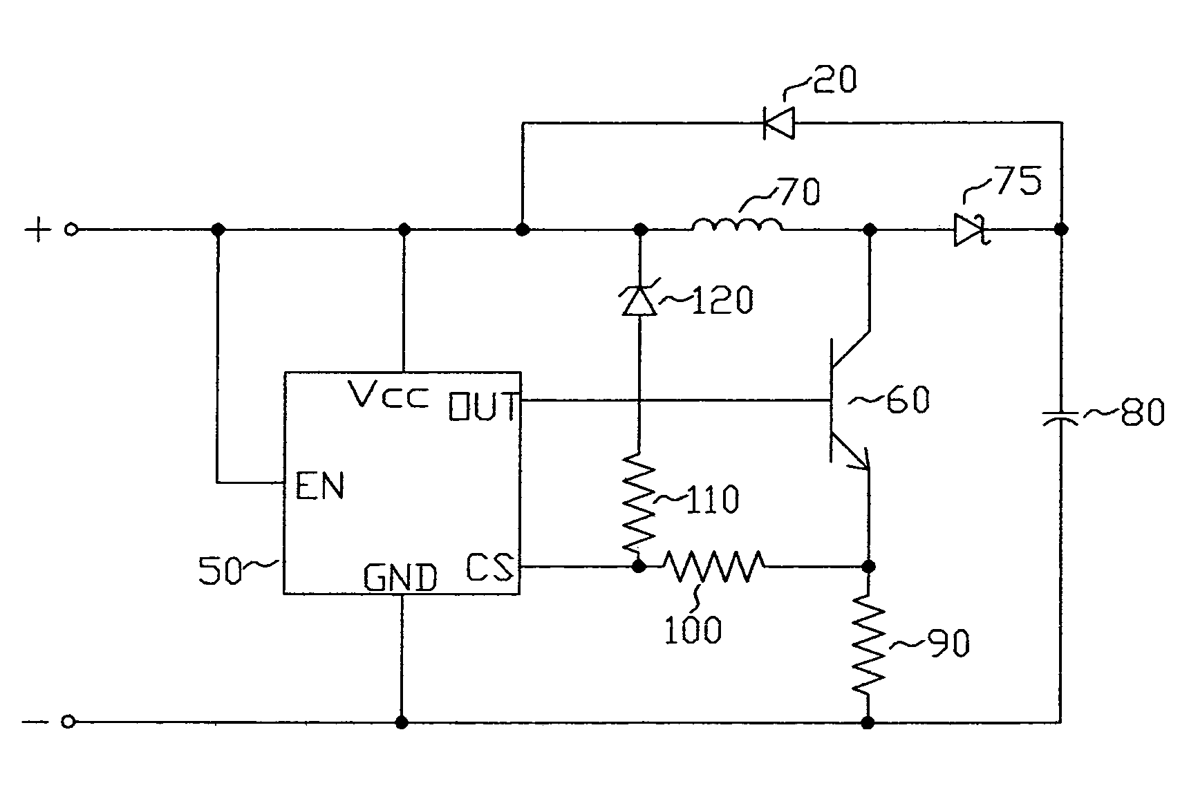
[0023]the second end of the current sense resistor is electrically connected to the negative terminal. In this circuit arrangement according to the present invention, the current sense series resistor and the bias resistor form a summing junction at the current sensing terminal of the control chip. As the input voltage is increased, the Zener diode supplies current to the bias resistor. Because the voltage at the current sense terminal is the result of the sum of the voltages created by the bias resistor and the current sense series resistor and has a fixed value, as the voltage contributed by the bias resistor increases, the voltage required across the current sense resistor to achieve the threshold value decreases. Thus the current through the current sense resistor decreases as voltage increases and constant energy storage in the inductor is achieved, resulting in constant power being delivered to the electrical component (e.g., the LED). This arrangement can thereby compensate in the event that higher stored energy is experienced, e.g., as a result of a higher input voltage.
[0024]The circuit device preferably further comprises a capacitor, a first end of the capacitor being electrically connected to a junction between the cathode end of the diode and the second component contact, a second end of the capacitor being electrically connected to a junction between the second end of the switch (or, where a current sense resister is present, the second end of the current sense resistor) and the negative contact. This capacitor serves to minimizes fluctuations resulting from the switching of the switch.
[0038]a second end of the current sense resistor is electrically connected to the negative terminal. In this circuit arrangement according to the present invention, the current sense series resistor and the bias resistor form a summing junction at the current sensing terminal of the control chip, and can thereby compensate in the event that higher stored energy is experienced, e.g., as a result of a higher input voltage.

Problems solved by technology

The circuitry of the ZXSC310 device lacks the ability to operate in the buck mode.

Method used


Image

  • Circuit devices, circuit devices which include light emitting diodes, assemblies which include such circuit devices, flashlights which include such assemblies, and methods for directly replacing flashlight bulbs
  • Circuit devices, circuit devices which include light emitting diodes, assemblies which include such circuit devices, flashlights which include such assemblies, and methods for directly replacing flashlight bulbs
  • Circuit devices, circuit devices which include light emitting diodes, assemblies which include such circuit devices, flashlights which include such assemblies, and methods for directly replacing flashlight bulbs

Examples


Embodiment Construction

[0051]As described above, in one aspect, the present invention is directed to a circuit device for providing energy to one or more electrical components (e.g., one or more LEDs), the circuit device comprising a positive contact, a negative contact, an inductor, a diode, a first component (e.g., LED) contact, a second component (e.g., LED) contact, a switch and a control device. The one or more electrical components to which energy is provided by the circuit device according to the present invention can be generally any device which operates at an elevated voltage (i.e., a voltage higher than the voltage of the energy source) and which depends on current regulation.

[0052]The positive contact and the negative contact can be any suitable structure for connection to a power source, e.g., a battery or a battery pack, a wide variety of such contacts being well known to those of skill in the art.

[0053]The inductor can be any suitable device which provides the function of an inductor, a wid...


PUM


Abstract

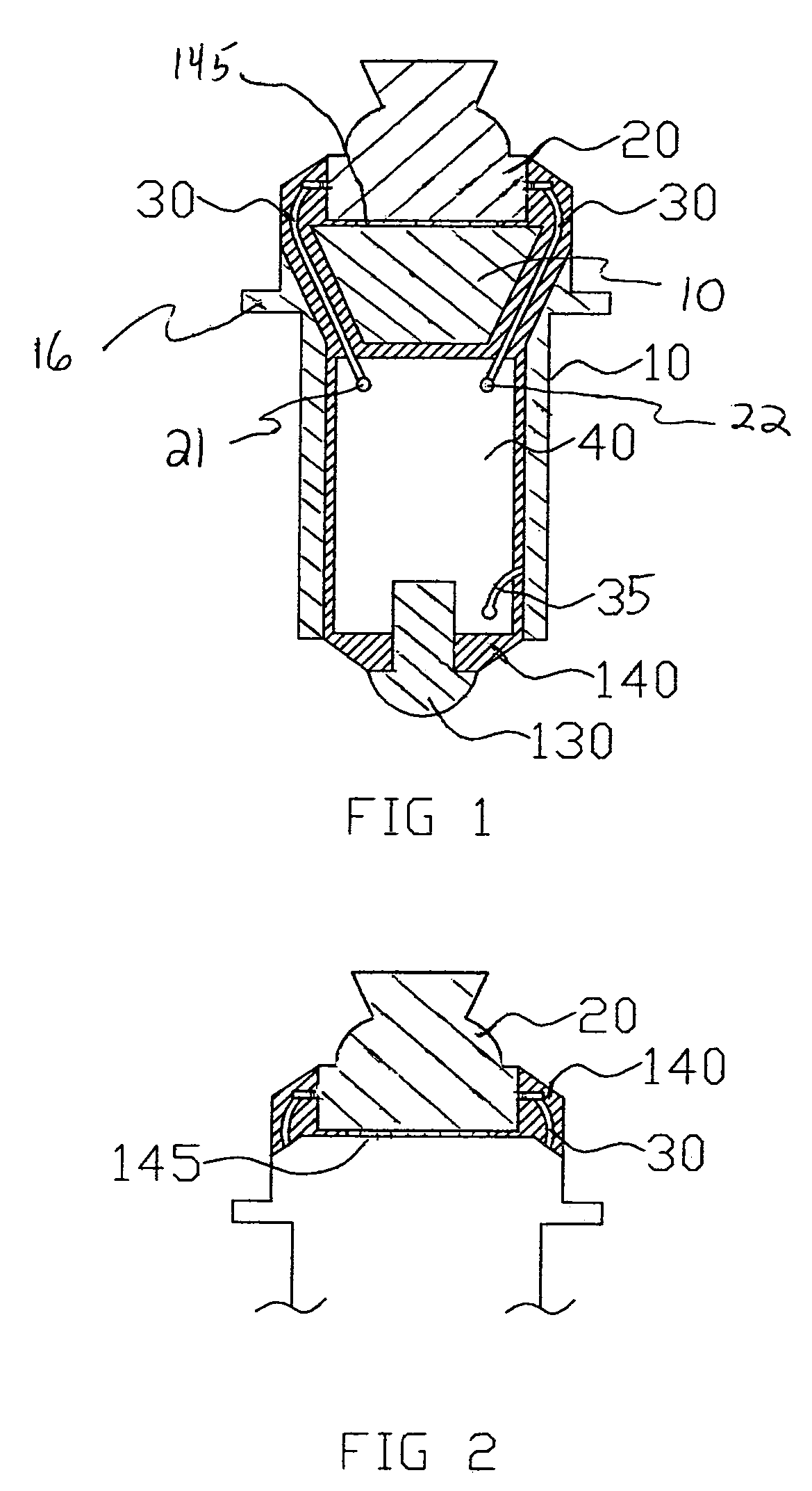
A circuit device for providing energy to at least one electrical component, such as a light emitting diode (LED). The circuit device comprises a positive contact, an inductor, a diode and a negative contact in series. A first component contact for electrical connection to a cathode end of an electrical component, a second component contact for electrical connection to an anode end of an electrical component, a switch and a control device are also included. The first component contact is electrically connected to a junction between the positive contact and one end of the inductor; and the second component contact is electrically connected to a cathode end of the diode. There are also provided a circuit device further including an LED, an assembly including a circuit device and a bulb base, a flashlight including an assembly, and a method of directly replacing a flashlight bulb.

Description

CROSS-REFERENCE TO RELATED APPLICATIONS[0001]This application claims the benefit of U.S. Provisional Patent Application No. 60 / 453,253, filed Mar. 10, 2003, the entirety of which is incorporated herein by reference.FIELD OF THE INVENTION[0002]The present invention relates to a circuit device, for providing energy to one or more electrical components, e.g., one or more light emitting diodes, an assembly including such a circuit device, as well as a circuit device including one or more light emitting diodes, an assembly which includes one or more light emitting diodes and a flashlight which includes such an assembly. The present invention further relates to a light emitting diode assembly for direct replacement of a flashlight bulb, as well as a method of directly replacing a flashlight bulb in a flashlight.BACKGROUND OF THE INVENTION[0003]Heretofore, flashlights incorporating light emitting diodes (LEDs) as their light sources have typically employed one or more high intensity, five ...

Claims


Application Information

Patent Timeline
Patent Type & Authority Patents(United States)
IPC IPC(8): F21L4/02H05B37/02H05B44/00
CPCH05B33/0815H05B33/0803F21K9/13F21Y2101/02Y02B20/346F21K9/23F21Y2115/10Y02B20/30H05B45/3574H05B45/38
Inventor MCGRATH, WILLIAM R.
Owner LEDDYNAMICS
Learn More