Plasma generation system having a refractor

a technology of plasma generation system and refractor, which is applied in the direction of plasma technique, chemical vapor deposition coating, arc welding apparatus, etc., can solve the problems of non-uniform etching profile and inability to form plasma uniformly

Active Publication Date: 2006-03-21
SAMSUNG ELECTRONICS CO LTD
View PDF6 Cites 6 Cited by
  • Summary
  • Abstract
  • Description
  • Claims
  • Application Information

AI Technical Summary

Benefits of technology

[0019]The present invention provides a plasma generation system that generates uniform high-density plasma for processing a device using a substrate having a large diameter, such as a 300 mm LCD, by providing a dielectric lens and preferably, a corrugated horn antenna.

Problems solved by technology

Thus, when plasma etching is performed on a large-sized substrate, etching is performed only in a narrow area of the substrate and an etching profile becomes non-uniform.
Resultantly, plasma cannot be formed uniformly when a substrate has a large diameter.

Method used


Image

  • Plasma generation system having a refractor
  • Plasma generation system having a refractor
  • Plasma generation system having a refractor

Examples


Embodiment Construction

[0023]Korean Patent Application No. 2003-2723, filed on Jan. 15, 2003, and entitled: “Plasma Generation System,” is incorporated by reference herein in its entirety.

[0024]The present invention will now be described more fully hereinafter with reference to the accompanying drawings, in which a preferred embodiment of the invention is shown. The invention may, however, be embodied in different forms and should not be construed as limited to the embodiments set forth herein. Rather, these embodiments are provided so that this disclosure will be thorough and complete, and will fully convey the scope of the invention to those skilled in the art. Like reference numerals refer to like elements throughout.

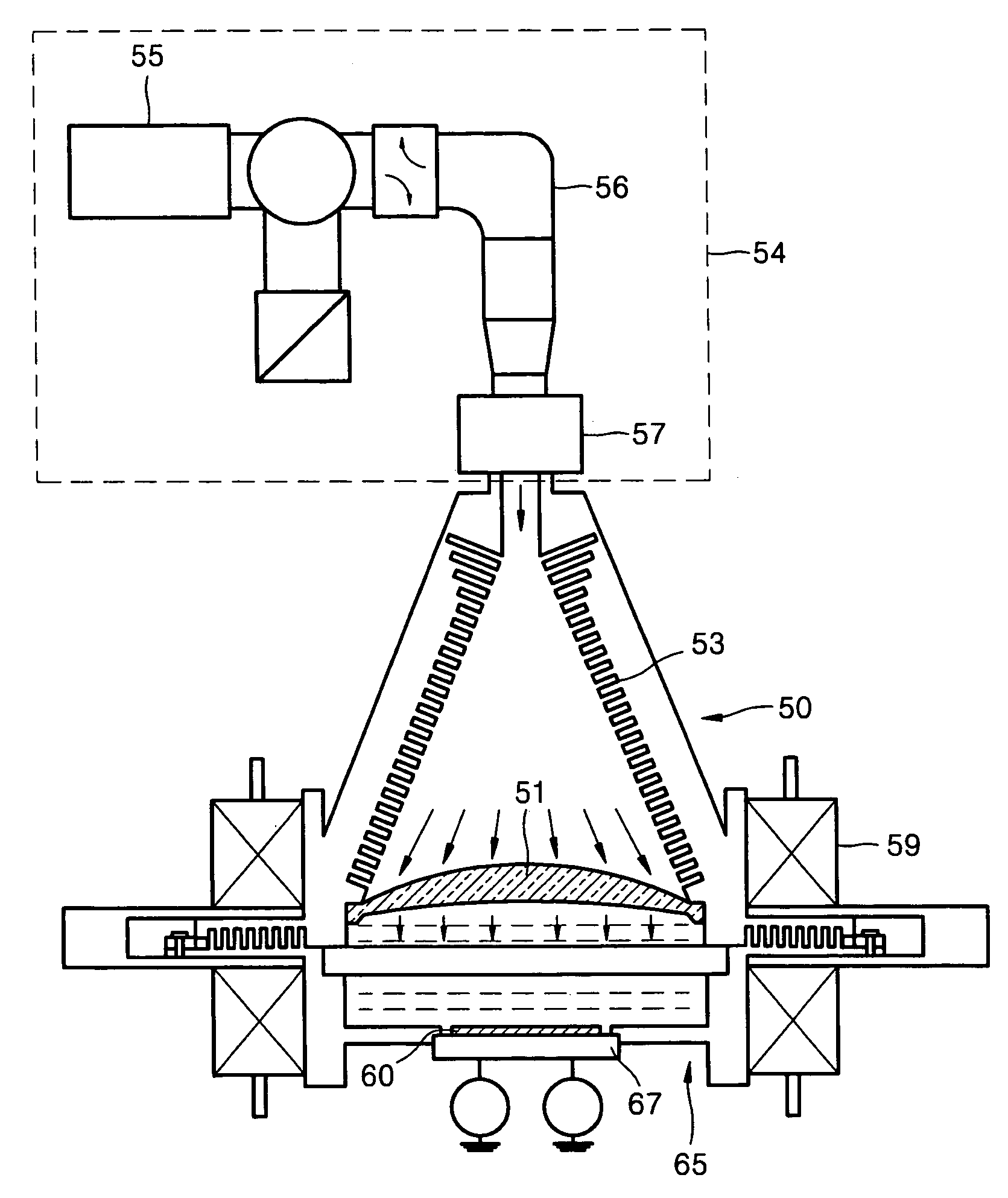
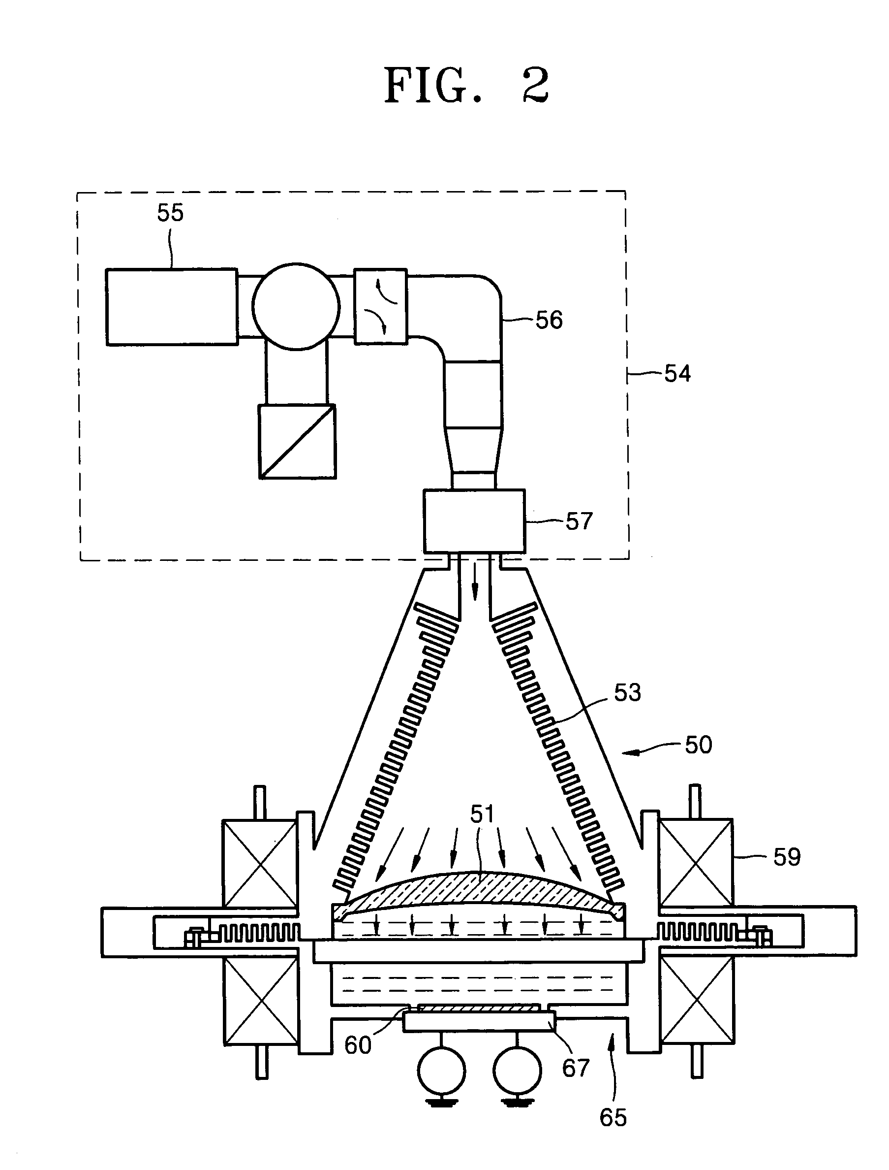
[0025]FIG. 2 schematically illustrates a structure of a plasma generation system according to an embodiment of the present invention. Referring to FIG. 2, the plasma generation system according to the embodiment of the present invention includes a microwave generator 54, a microwave transf...


PUM

PropertyMeasurementUnit
radio frequencyaaaaaaaaaa
frequencyaaaaaaaaaa
diameteraaaaaaaaaa

Abstract

A plasma generation system that is capable of generating uniform high-density plasma includes a microwave generator for generating microwaves, a refractor for altering a direction of propagation of the microwaves, and an electromagnetic unit for applying a magnetic field to plasma formed by the microwaves to generate electron cyclotron resonance (ECR).

Description

BACKGROUND OF THE INVENTION[0001]1. Field of the Invention[0002]The present invention relates to a plasma generation system. More particularly, the present invention relates to a plasma generation system that generates uniform high-density plasma.[0003]2. Description of the Related Art[0004]FIG. 1 schematically illustrates a structure of a conventional electron cyclotron resonance (ECR) plasma device.[0005]Referring to FIG. 1, a shower plate 13 is installed in an upper portion inside a processing chamber 11. A gas for forming plasma is supplied into the processing chamber 11 over a substrate 10 via the shower plate 13. The substrate 10 is seated on a substrate holder 17. A radio frequency bias in a range of 100 kHz to 15 MHz is applied from a radio frequency power source 29 to the substrate holder 17 via a matching network 27.[0006]An etching gas is supplied into the processing chamber 11 via a gas inlet 19. Electromagnetic waves having an ultra-high frequency in a range of 300 MHz ...

Claims


Application Information

Patent Timeline
Patent Type & Authority Patents(United States)
IPC IPC(8): B23K10/00H05H1/18H01J37/32H01L21/3065H05H1/46
CPCH01J37/32192H05H1/46H01J37/32678H01J37/32266H05H1/18
Inventor PETRIN, ANDREIHUR, JI-HYUNSHIN, JAI-KWANG
Owner SAMSUNG ELECTRONICS CO LTD
Why Eureka
Try Eureka