Device for damping torsional vibrations

a technology of torsional vibration and damping device, which is applied in the direction of dynamo-electric machines, electrical apparatus, portable lifting, etc., can solve the problems of limited torsional capacity of components with respect to each other, and achieve the effect of effective damping of torsional vibration, simple structural design, and reasonable cos

Inactive Publication Date: 2006-03-21
KARL HEINZ LINNIG GMBH & CO KG
View PDF7 Cites 33 Cited by
  • Summary
  • Abstract
  • Description
  • Claims
  • Application Information

AI Technical Summary

Benefits of technology

[0011]The invention is designed to transmit torques of internal combustion engines in a contactless manner to auxiliary assemblies utilizing a simple structural design that can be produced at a reasonable cost. The novel device can transmit torques in the no-load region or in the partial-load region or in the full-load region, while effectively dampening torsional vibrations with low maintenance without wear and preventing superpositions. This unit is not intended to replace the coupling function of a friction or magnetic coupling which has to be actuated intermittently.
[0012]Taking the features of a device for dampening torsional vibrations having a driving and a driven component having magnets disposed opposite each other on the drive and driven components as the starting point, this object is achieved by the arrangement of the magnets in axial alignment in a first substantially circular path (15) on substantially flat confronting surfaces on the drive component and driven component and an intermittently contactable carry along disposed in a different circular path. The features of the invention including the arrangement of the magnets, their accommodation of full and partial loads the use of mechanical stops, the dimensioning of the magnet pairs to the carry along mechanism all permit advantageous implementations and developments of the invention.
[0013]The device according to the invention for damping torsional vibrations provides two components which can be twisted with respect to each other in a limited manner, have a common geometrical axis of rotation and have, on opposite surfaces, magnets which can be twisted with respect to each other together with the particular component. The limited torsional capacity of the components with respect to each other means that the latter have play or limited freewheeling with respect to each other and in which there is no mechanical contact between them in one direction of rotation or an opposed direction of rotation. In this tolerance band, it is only the forces which act between the magnets which determine the behavior of the components with respect to rotation about the common geometrical axis of rotation. This has the effect of achieving, between the components, a wear-free, contactless coupling which has vibration-damping properties due to the restoring forces of the interacting magnets upon twisting of the components. These vibration-damping properties are not only available during idling, i.e. when rotation is absent, but also during driving, and as long as the forces which act between the magnets are sufficient in order to transmit the supplied torque. This entirely avoids mechanical contact of the components in one direction of rotation, even during operation under load, and therefore achieves optimum decoupling of drive and output.

Problems solved by technology

The limited torsional capacity of the components with respect to each other means that the latter have play or limited freewheeling with respect to each other and in which there is no mechanical contact between them in one direction of rotation or an opposed direction of rotation.

Method used


Image

  • Device for damping torsional vibrations
  • Device for damping torsional vibrations
  • Device for damping torsional vibrations

Examples


Embodiment Construction

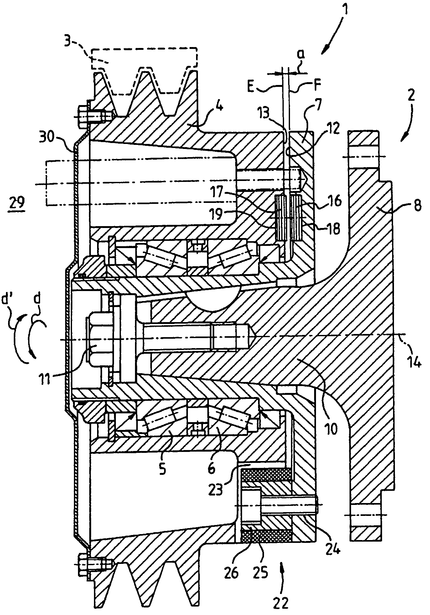
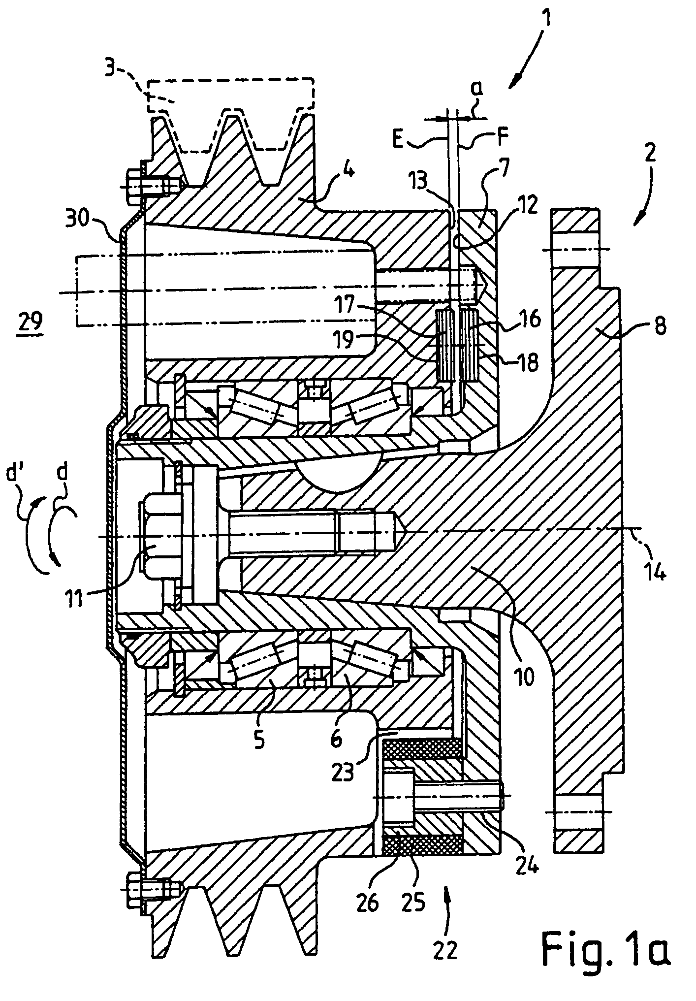
[0039]FIG. 1a illustrates a first embodiment of a device 1 according to the invention. The device 1 is provided for use between a driving machine (not illustrated), such as, for example, an internal combustion engine, and an auxiliary assembly 2 which is to be driven by the driving machine, such as, for example, a compressor for an air conditioning system or an additional electric generator. In the present exemplary embodiment, the device 1 is driven via a belt 3 on a belt pulley 4 of the device 1. The device 1 essentially comprises the belt pulley 4 and an opposite pulley 7 which is mounted rotatably therein via rolling bearings 5, 6. The opposite pulley 7 accommodates, in a rotationally fixed manner, a flange 8 which belongs to the auxiliary assembly 2 and is threaded to a drive shaft 9 (not illustrated) of the auxiliary assembly 2. The rotationally fixed connection between the opposite pulley 7 and the flange 8 takes place by means of a clamping cone 10 which is formed on the fla...


PUM


Abstract

The invention relates to a device (1) for damping torsional vibrations, having a driving and a driven component (4, 7). Provision is made in this case to provide between the components individual magnets (16, 17) which lie opposite each other and can be displaced in a limited manner with respect to each other in an angular range, the torsional capacity of the two components with respect to each other being limited by mechanical stops (22).

Description

CROSS REFERENCE TO RELATED APPLICATIONS[0001]Not applicable.STATEMENT REGARDING FEDERALLY SPONSORED RESEARCH OR DEVELOPMENT[0002]Not applicable.INCORPORATION-BY-REFERENCE OF MATERIAL SUBMITTED ON COMPACT DISC[0003]Not applicable.REFERENCE TO A “MICROFICHE APPENDIX”[0004]Not applicable.BACKGROUND OF THE INVENTION[0005](1) Field of the Invention[0006]The invention relates to a coupling-free unit for the transmission of torque and damping of torsional vibrations for motor vehicles, boats and other forms of transportation having an internal combustion engine for driving auxiliary assemblies, such as, for example, a fan, a compressor of an air conditioning system, an electric generator, water pump, hydraulic pump, or a compressor for the brake system driven by the internal combustion engine.[0007]The invention furthermore relates to a unit for the contactless transmission of torque and damping of torsional vibrations for motor vehicles and other forms of transportation having an internal...

Claims


Application Information

Patent Timeline
IPC IPC(8): F02B75/06F16F15/12F16F15/124F16F15/18F16H55/36
CPCF16F15/1207F16F15/124F16H55/36F16F15/18F16H2055/366
Inventor LINNIG, KARL-HEINZ
Owner KARL HEINZ LINNIG GMBH & CO KG
Why Eureka
Try Eureka