
Hierarchical parallel pipelined operation of analog and digital circuits

a pipelined operation and analog and digital circuit technology, applied in the field of high-throughput discrete-time systems with parallel pipelined architectures, can solve the problems of front-end bandwidth not being scaled down to match the slow clock, backend limiting system clock frequency,

Active Publication Date: 2006-03-14
AVAGO TECH INT SALES PTE LTD
View PDF4 Cites 27 Cited by
  • Summary
  • Abstract
  • Description
  • Claims
  • Application Information

AI Technical Summary

Benefits of technology

[0009]The present invention relates to a hierarchical pipelined parallel operation of analog/d

Problems solved by technology

The problem with this approach is that the slow running block in the backend limits the system clock frequency.
However, the front-end bandwidth can not be scaled-down to match the slow clock, because the front-end has to track the fast varying signal, and / or the matching or noise (kT / C) requirements may prevent the scaling.
The front-end is usually the bottleneck in mismatch and noise because of the signal amplification in the front-end stage.

Method used


Image

  • Hierarchical parallel pipelined operation of analog and digital circuits
  • Hierarchical parallel pipelined operation of analog and digital circuits
  • Hierarchical parallel pipelined operation of analog and digital circuits

Examples


Embodiment Construction

[0025]Reference will now be made in detail to embodiments of the present invention, examples of which are illustrated in the accompanying drawings.

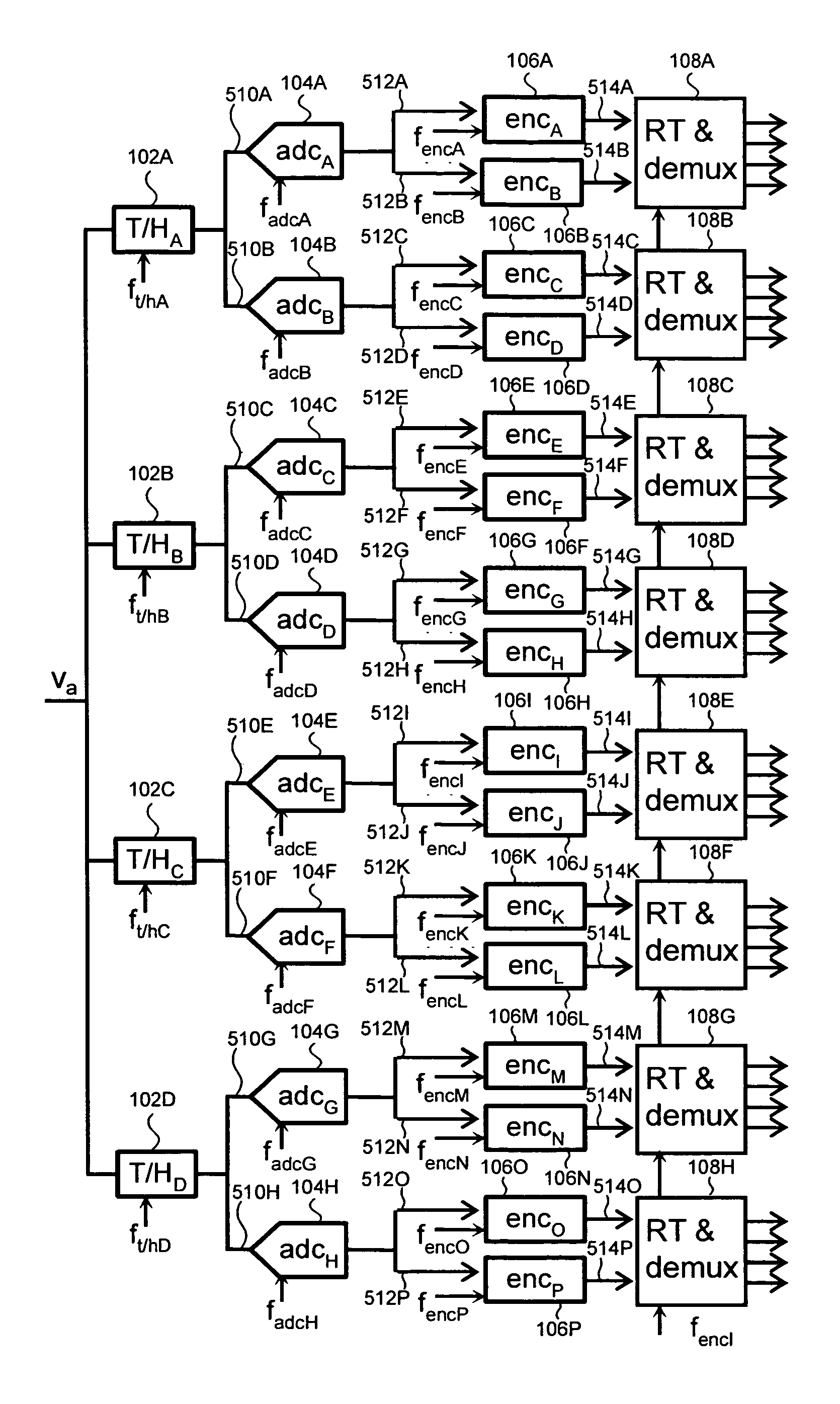
[0026]FIG. 2 shows the present invention in a generalized form. Shown in FIG. 2 are two stages “a” and “b” (of what can be a parallel hierarchy with more than two stages) of a device, with each stage having sampling devices M (Ma, Mb), analog or digital circuits A (Aa0–Aa2, Ab0–Ab5), clocked by the clock signals fa0–fa2 and fb0–fb5, with the data outputs sa0–sa2 and sb0–sb5, as shown in the figure. It will be appreciated that the number of devices in each stage is not limited to what is shown in FIG. 2.

[0027]The phase and frequency relationships between the various signals are illustrated in FIG. 3.

[0028]FIG. 4 illustrates how the multi-frequency multi-phase clock approach of FIGS. 2–3 may be applied to a programmable gain array, which, for example, can be one element of an ADC. Shown in FIG. 4 is a first stage comprising track-and-holds ...


PUM


Abstract

A hierarchical parallel pipelined circuit includes a first stage with a plurality of sampling circuits and a plurality of corresponding analog or digital circuits that receive an output from the plurality of sampling circuits. A second stage includes a second plurality of sampling circuits and a plurality of corresponding analog or digital circuits that receive an output from the plurality of sampling circuits. A multi-frequency, multi-phase clock clocks the first and second stages, the multi-frequency, multi-phase clock providing a first clock having a first frequency having either a single or plurality of phases, and a second clock having a second frequency having a plurality of phases. A first phase of a plurality of phases is phase locked to the first phase of the first clock. The clock frequency multiplied by the number of parallel devices in each stage is the throughput of the circuit and is kept constant across the stages.

Description

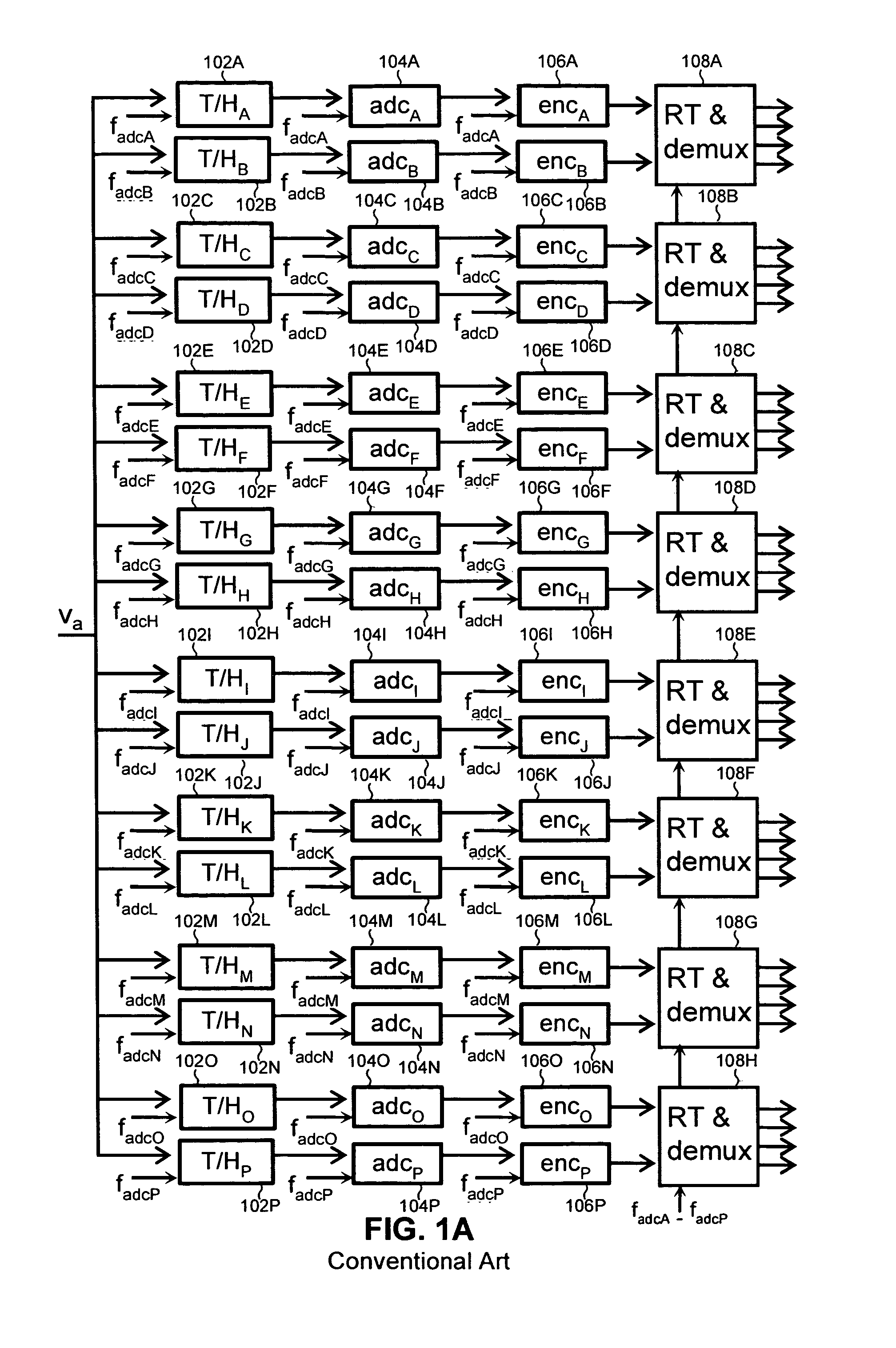
BACKGROUND OF THE INVENTION[0001]1. Field of the Invention[0002]The present invention is related to high-throughput discrete-time systems with parallel pipelined architectures, and more particularly, to high-speed analog front-end circuits, such as time-interleaved analog-to-digital converters and to programmable gain amplifiers that precede the analog-to-digital converters.[0003]2. Related Art[0004]Many modern data communications systems use parallel pipelined architectures in order to increase the data throughput. In essence, this approach utilizes a number of identical pipelined sub-circuits arranged in parallel. Another term for this architecture is “time interleaving.”[0005]FIG. 1A illustrates a conventional time interleaved analog-to-digital converter (ADC). As shown in FIG. 1A, an analog voltage Va is sampled by track-and-hold amplifiers 102A–102P. The track-and-hold amplifiers 102A–102P are clocked by clocks fadcA–fadcP, as shown in the figure. The outputs of the track-and-h...

Claims


Application Information

Patent Timeline
IPC IPC(8): H03M1/38
CPCH03G3/001H03M1/1215H03K5/15013
Inventor PAN, HUIFUJIMORI, ICHIRO
Owner AVAGO TECH INT SALES PTE LTD
Learn More