
Radiation image pick-up device and radiation image pick-up method

a technology of radiation image and pickup device, which is applied in the direction of radioation controlled devices, television systems, instruments, etc., can solve the problems of reduced frame frequency, reduced operation speed, and current may not flow, and achieve stable and high-speed moving image photographing, reduce cost and dark current, and reduce voltage fluctuations. effect of gnd

Inactive Publication Date: 2006-03-14
CANON KK
View PDF7 Cites 84 Cited by
  • Summary
  • Abstract
  • Description
  • Claims
  • Application Information

AI Technical Summary

Benefits of technology

The present invention provides a radiation image pick-up device and method that can restrain voltage fluctuations, dispense with frame-by-frame wait periods, and achieve stable and high speed moving image photographing. The device includes a radiation detecting circuit section with pixels arranged over a substrate, and a drive circuit section for driving the circuit. The device also has a wavelength converter for converting the wavelengths of the radiations. The invention solves the problems of previous devices by providing a method for reading the conversion elements in a way that reduces voltage fluctuations and allows for stable and high speed moving image photographing. The device is also cost-effective and can suppress dark current.

Problems solved by technology

However, if the duration of the photoelectric conversion mode becomes unusually long or the illuminance of the incident light is unusually intense for some reason or other, a current may fail to flow even though light does come incident.
This gives rise to a particular problem that, when moving images are to be acquired, the frame frequency is reduced, namely the operation speed slows down.
As described so far, the prior art according to which all the photoelectric conversion elements are refreshed once per frame of read operation involves a problem of difficulty to photograph moving images.
Similarly, the noise voltage will also drop, but there also is a problem that, because the noise components in the read circuit section 702 at the later stage, including so-called circuit noises such as thermal noise of resistances and the shot noise of transistors, are not zero, the eventual S / N ratio of the system will drop.
To realize this, the element size of the transistors constituting the amplifier will become huge, resulting in a greatly increased chip size.
This would invite a greater current consumption, and lead to a secondary problem of requiring a cooling mechanism against the resultant heat emission.
However, voltages due to accumulated charges in the photoelectric conversion element are applied to the gate terminals of the source follower TFTs for a long period of time.
There generally is a problem that TFTs mainly made of amorphous silicon suffer fluctuations in gate threshold voltage (Vth), the indicator for turning TFTs on, due to electric field stresses working on their gate terminals.
There is a risk that the input rating of the read circuit may be surpassed if the threshold voltage Vth in the source follower TFTs varies, and if this risk actualizes, the read circuit may be destroyed.
In reality, the threshold voltage Vth of TFTs is uneven even at the time of shipment from the factory (at the time of TFT fabrication), and also varies while they are being operated.
However, they require two kinds of junctions including PI junction and IN junction, entailing a problem of an increased dark current.
This means a laminated structure for which TFTs and photoelectric conversion elements have to be separately fabricated, involving disadvantages in yield and cost.

Method used


Image

  • Radiation image pick-up device and radiation image pick-up method
  • Radiation image pick-up device and radiation image pick-up method
  • Radiation image pick-up device and radiation image pick-up method

Examples


Embodiment Construction

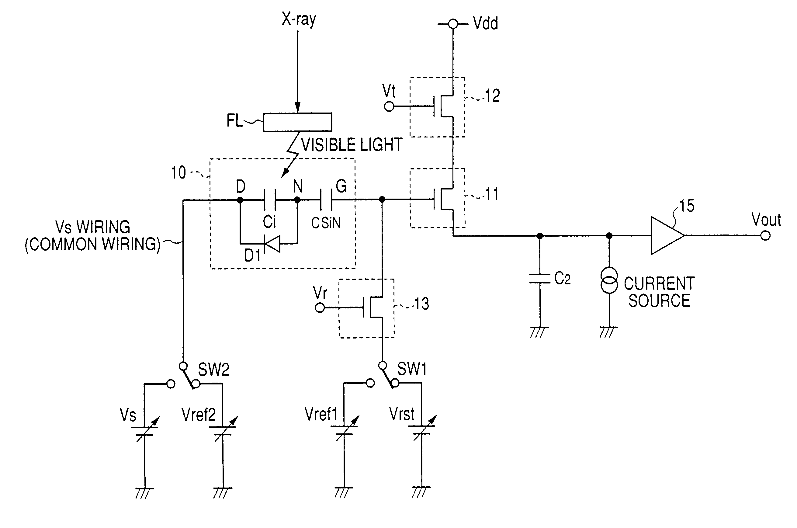
[0103]Now will be described a radiation image pick-up device and a radiation image pick-up method embodying the invention with reference to accompanying drawings. The following description of the preferred embodiment of the invention will refer to a radiation image pick-up device having a substrate over which a photoelectric conversion array is formed, the device using, as in the conventional device described above, MIS-type photoelectric conversion elements and, as the semiconductor material for field effect transistors, an amorphous silicon semiconductor film. Although the embodiment of the invention to be described uses the X-ray as radiations, the invention is not limited to them but the applicable radiations include electromagnetic waves such as the γ-ray as well as the α-ray and the β-ray.

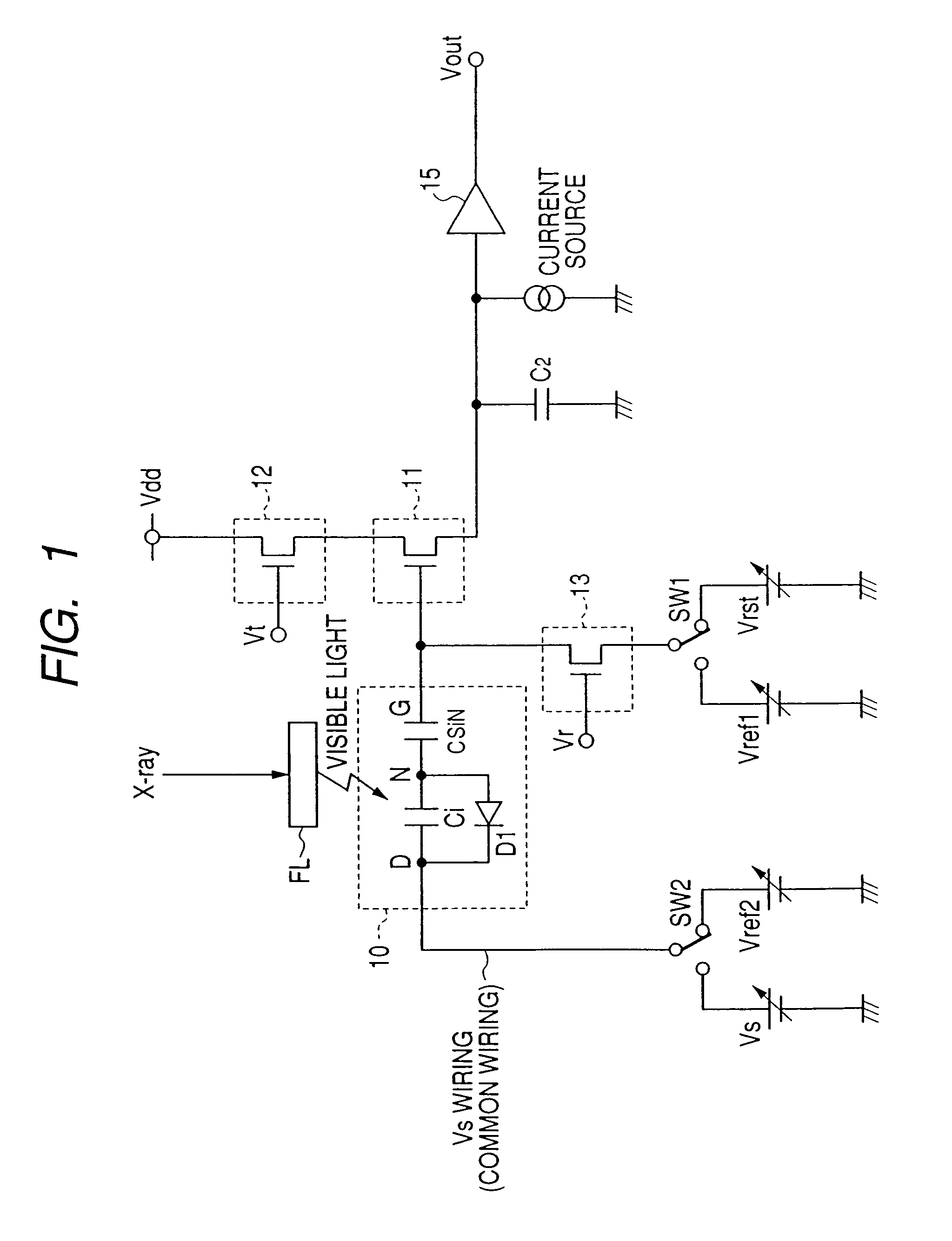
[0104]FIG. 1 is a circuit diagram of a one-pixel equivalent of an X-ray image pick-up device in the preferred embodiment of the invention.

[0105]As shown in FIG. 1, an MIS-type photoelectric c...


PUM


Abstract

A radiation image pick-up device which can restrain voltage fluctuations on GND and power supply lines, dispense with frame-by-frame wait periods, make possible stable and high speed moving image photographing, and are reduced in cost and dark current is to be provided.In pixels for detecting incident radiations, there are provided MIS-type conversion elements for converting the radiations into electric signals, source follower-type first TFTs for reading out the electric signals, second TFTs which so operate as to read out of the first TFTs the electric signals of the conversion elements selected by a drive circuit section on a row-by-row basis, and third TFTs which so operate as to reset or refresh on a row-by-row basis the conversion elements out of which reading by the first TFTs has been accomplished.

Description

[0001]This application is a continuation of International Application No. PCT / JP2004 / 017661, filed on Nov. 22, 2004, which claims the benefit of Japanese Patent Application No. 2003-408032 filed on Dec. 5, 2003.BACKGROUND OF THE INVENTION[0002]1. Field of the Invention[0003]The present invention relates to a radiation image pick-up device and a radiation image pick-up method which can be suitably used in medical diagnoses and industrial non-destructive inspections. Radiations in the context of this specification include the X-ray, γ-ray, α-ray and β-ray.[0004]2. Related Background Art[0005]X-ray photographing systems conventionally installed in hospitals and elsewhere use either one of two systems, the film photographing system by which a film is exposed to X-rays irradiating and transmitted by a patient and the image processing system by which X-rays transmitted by a patient are converted into electric signals and subjected to digital image processing.[0006]One of the available dev...

Claims


Application Information

Patent Timeline
Patent Type & Authority Patents(United States)
IPC IPC(8): G01T1/24G01T1/20H01L27/14H01L27/146H04N5/32H04N5/361H04N5/369H04N5/376
CPCH04N5/32H01L27/14658H04N25/30H04N25/77
Inventor ENDO, TADAO
Owner CANON KK
Learn More