Vehicle control apparatus
- Summary
- Abstract
- Description
- Claims
- Application Information
AI Technical Summary
Benefits of technology
Problems solved by technology
Method used
Image
Examples
first embodiment
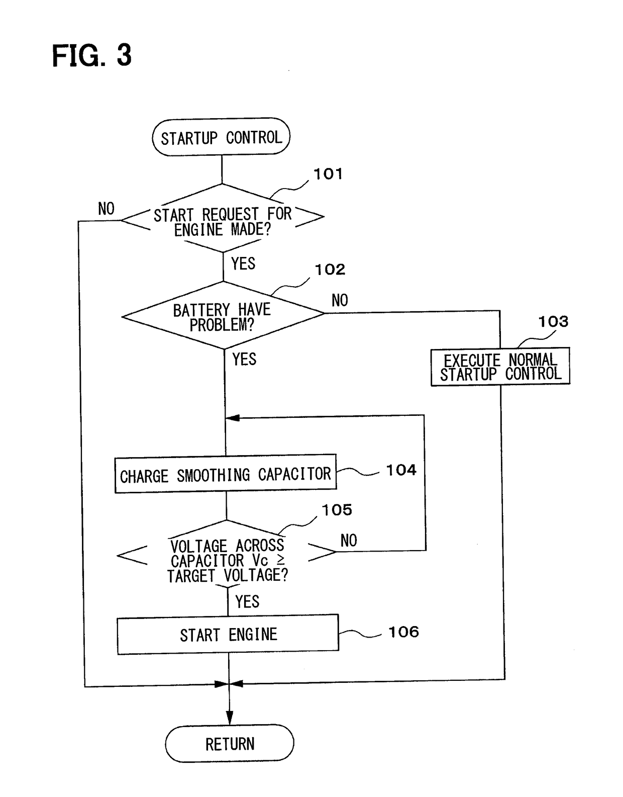
[0021]A first embodiment of the present disclosure will be described with reference to FIG. 1 to FIG. 3.
[0022]A schematic configuration of a vehicle drive control system will be described with reference to FIG. 1.
[0023]An engine 11 which is an internal combustion engine is mounted as a power source of a vehicle. Power of an output shaft (a crankshaft) of the engine 11 is transmitted to a transmission 12, and power of an output shaft of the transmission 12 is transmitted to wheels 15 via a differential gear mechanism 13, an axle 14, and the like. The transmission 12 may be a stepped transmission by which a gear position is shifted stepwise from multiple gear positions or a continuously variable transmission (CVT) by which the gear is shifted steplessly. The transmission 12 incorporates a clutch 16 for intermitting power transmission. The clutch 16 may be a hydraulic clutch driven hydraulically or an electromagnetic clutch driven electromagnetically. The clutch 16 may be provided sepa...
second embodiment
[0046]A second embodiment in which the present disclosure is applied to a hybrid vehicle will now be described with reference to FIG. 4 to FIG. 6. Note, however, that a part substantially identical to that of the first embodiment will be denoted by the reference numeral identical to that of the first embodiment and not be described or described in a simplified manner, whereby a part different from the first embodiment will mainly be described.
[0047]In the second embodiment, an engine 11 and a traveling motor generator (MG) 28 are mounted as power sources of a vehicle as illustrated in FIG. 4. Power of an output shaft of the traveling MG 28 is transmitted to wheels 15 via a differential gear mechanism 29, an axle 14, and the like. An MG inverter 30 for driving the traveling MG 28 is connected to a high-voltage battery 19, so that the traveling MG 28 exchanges power with the high-voltage battery 19 via the MG inverter 30.
[0048]As illustrated in FIG. 5, a smoothing capacitor 26 is conn...
third embodiment
[0065]A third embodiment in which the present disclosure is applied to a hybrid vehicle will now be described with reference to FIG. 7 to FIG. 9. Note, however, that a part substantially identical to that of the second embodiment will be denoted by the reference numeral identical to that of the second embodiment and not be described or described in a simplified manner, whereby a part different from the second embodiment will mainly be described.
[0066]In the third embodiment, a boost converter 31 is connected between a high-voltage battery 19 and an MG inverter 30 as illustrated in FIG. 7. The boost converter 31 has a function of boosting a voltage on the side of the high-voltage battery 19 and outputting the voltage to the side of the MG inverter 30, and a function of stepping down a voltage on the side of the MG inverter 30 and outputting the voltage to the side of the high-voltage battery 19.
[0067]As illustrated in FIG. 8, a smoothing capacitor 26 is connected between the boost co...
PUM
 Abstract
Description
Claims
Application Information
 - R&D
- Intellectual Property
- Life Sciences
- Materials
- Tech Scout
- Unparalleled Data Quality
- Higher Quality Content
- 60% Fewer Hallucinations
Browse by: Latest US Patents, China's latest patents, Technical Efficacy Thesaurus, Application Domain, Technology Topic, Popular Technical Reports.
© 2025 PatSnap. All rights reserved.Legal|Privacy policy|Modern Slavery Act Transparency Statement|Sitemap|About US| Contact US: help@patsnap.com


