
Erosion-resistant hydrocyclone liner

a hydrocyclone liner and erosion-resistant technology, applied in the direction of solid separation, wet separation, single direction vortex, etc., can solve the problems of hydrocyclones that have been expected to experience greater wear, liquid/liquid hydrocyclone erosion is a serious problem in certain installations, and the engineering of a liquid/liquid hydrocyclone liner that is both erosion-resistant and can support its own weight is challenging

Active Publication Date: 2006-03-14
PETRECO INT
View PDF12 Cites 29 Cited by
  • Summary
  • Abstract
  • Description
  • Claims
  • Application Information

AI Technical Summary

Benefits of technology

"The present invention is about improving erosion-resistant liquid / liquid hydrocyclone liners by using a composite construction made of different materials. The invention recognizes that hydrocyclone liners tend to suffer the most significant damage from erosion in the areas where fluid velocities are greatest. The inventors have created a hydrocyclone liner that includes a head section made of a highly erosion-resistant material, such as tungsten carbide, and a separate separation section made of a less erosion-resistant but more physically durable material. The head and separation sections are removably affixed to each other. The separation section is also provided with structural supports to provide mechanical strength and resistance to bending. The invention helps to keep the cost and weight of the liners within acceptable parameters while still providing effective erosion resistance."

Problems solved by technology

As a result of these structural differences, the engineering of a liquid / liquid hydrocyclone liner that is both erosion-resistant and which can support its own weight is challenging.
It is noted that erosion resistance has heretofore not been considered as important a design consideration for liquid / liquid hydrocyclone liners as for liquid / solid hydrocyclone liners, since liquid / solid hydrocyclones have been expected to experience greater wear due to the large amount of solids present in the material being separated.
In fact, however, erosion of liquid / liquid hydrocyclones is a serious problem in certain installations.
This is not generally an available option for narrow bore liquid / liquid liners, such as is used in petroleum fluid processing.
Access to the interior surfaces of the liner is limited due to the small diameter (typically less than 2″) of portions of the liner, and the length of the liner makes an even and complete coating unlikely.
Further, only a limited number of suitable coating treatments are known that will harden the steel of the liner against erosion without compromising its corrosion resistant properties.
Erosion-resistant materials, such as ceramics or certain alloys, may be very heavy or brittle, such that the construction of the entire liner from such erosion-resistant material is not desirable.
A hydrocyclone liner comprised entirely of an erosion-resistant material, such as tungsten carbide, might not be fit for service due to poor mechanical properties (including weight and tensile strength) and high cost.
During installation, then, a heavy and brittle liner might easily be damaged.
For one reason or another, however, these prior art designs are unsatisfactory and / or do not provide an acceptable design for an erosion resistant liquid / liquid hydrocyclone liner.
The Day et al. design does not provide adequate erosion protection for the inner surfaces associated with the inlet portion of the hydrocyclone because the erosion protection is only provided at and around the reduced diameter portion of the hydrocyclone.
However, the velocity of particles entering the hydrocyclone at the inlet portion does result in significant erosion at and near the inlet portion.
's design does nothing to prevent or slow this erosion.
This difference in dimensions ensures that Metcalf's design is unsuitable for liquid / liquid hydrocyclones.

Method used


Image

  • Erosion-resistant hydrocyclone liner
  • Erosion-resistant hydrocyclone liner
  • Erosion-resistant hydrocyclone liner

Examples


Embodiment Construction

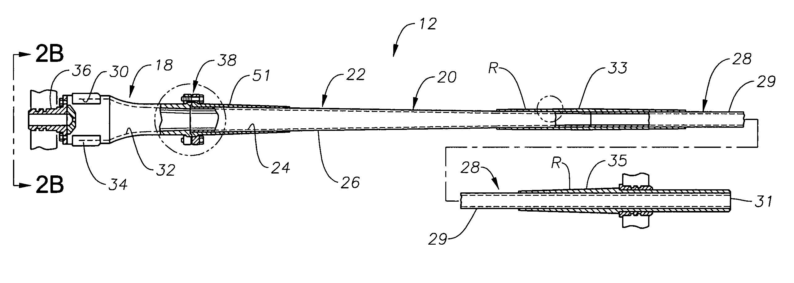
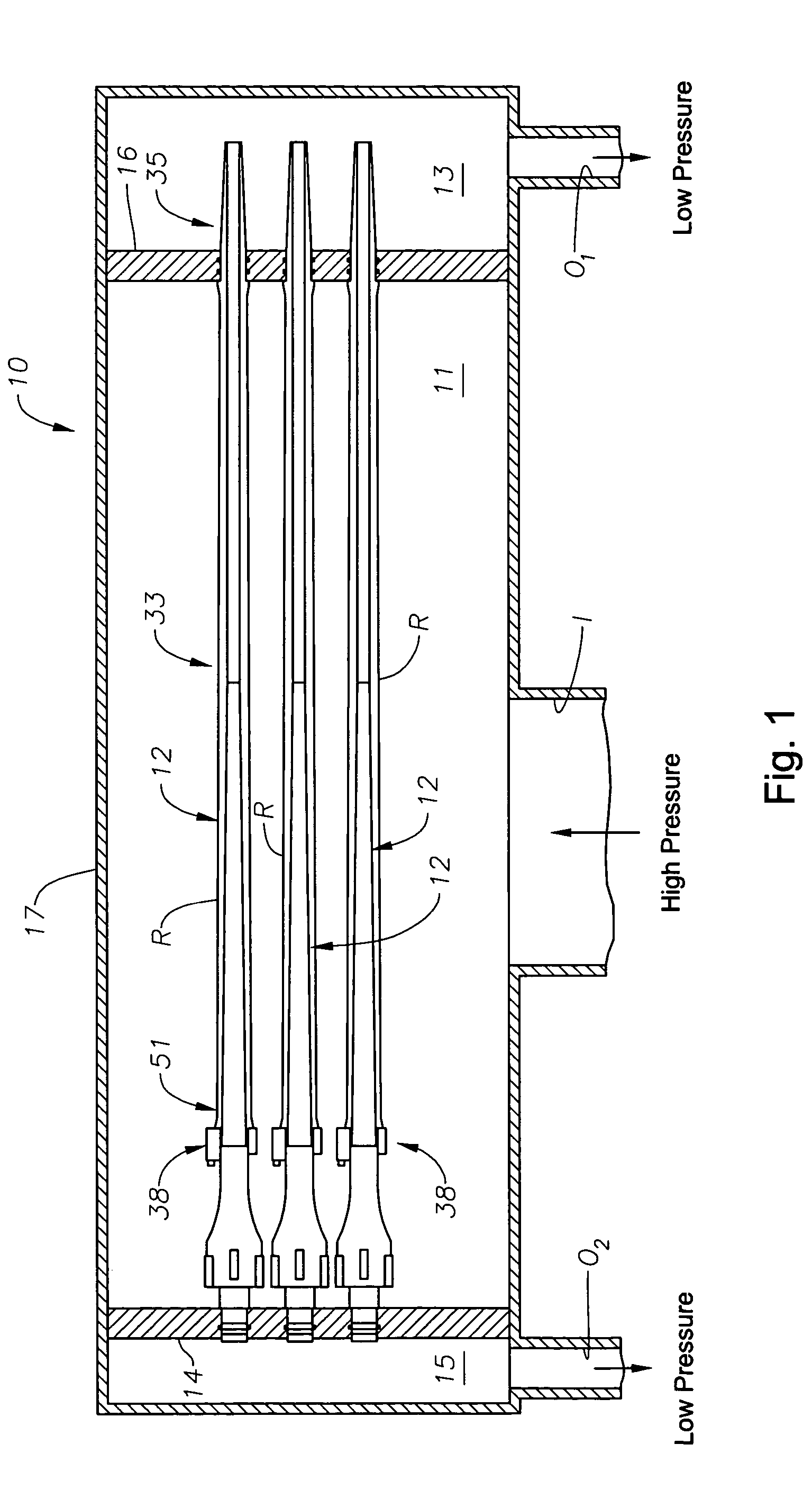
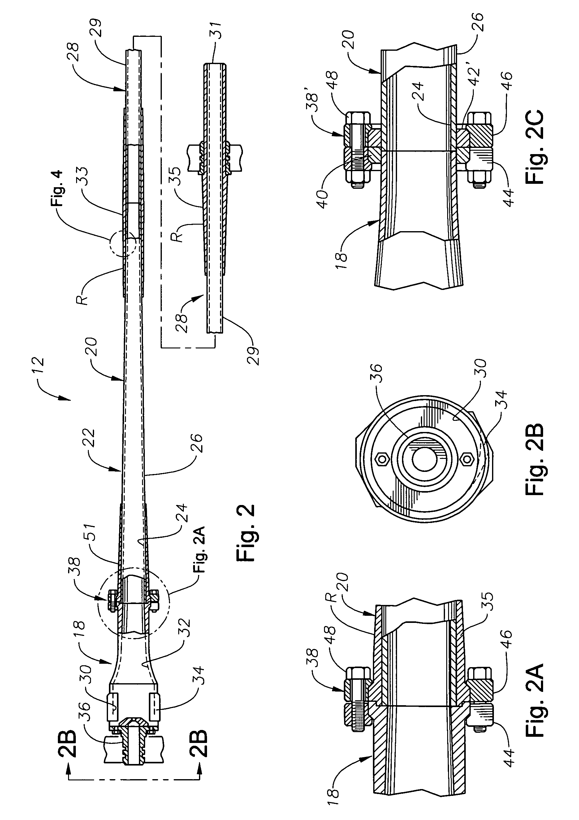
[0035]FIG. 1 illustrates a portion of a hydrocyclone assembly 10, of a type known in the art, having a plurality of hydrocyclones, or liners, 12 that separate fluid components of a fluid mixture. Those of skill in the art will understand that the hydrocyclone assembly 10 includes numerous other components and systems that are not germane to the present invention and, therefore, are not described in any detail here. Two support plates 14 and 16, which are located proximate opposite ends of the hydrocyclones 12, support the hydrocyclones 12. The two support plates 14, 16 are installed within a hydrocyclone vessel 17 having a fluid inlet I, underflow outlet O1 and reject outlet O2. A fluid mixture enters the fluid inlet I into central chamber 11. Fluids separated by the hydrocyclones 12 are emptied into the underflow chamber 13 and reject chamber 15. As indicated by FIG. 1, a fluid mixture enters the inlet I under high fluid pressure, and there is lower fluid pressure proximate the res...


PUM


Abstract

Erosion-resistant liquid / liquid hydrocyclone liners, wherein the weight and cost of the liners are kept within acceptable parameters through the construction of a composite hydrocyclone liner, comprised of two or more different materials. The hydrocyclone liner includes a head section that is fashioned, primarily, of a highly erosion-resistant material, such as tungsten carbide. The liner also includes a separate separation section that is primarily fashioned of a material that may be less erosion-resistant but which is less brittle and more physically durable than that used to construct the head section. As a result of this composite construction, the liner is less likely to fail mechanically during installation or use. The head and separation sections are removably affixed to one another. The separation section of the hydrocyclone liner is provided with one or more structural supports to provide mechanical strength and resistance to bending. A liner is also described having a removable involute insert of highly erosion resistant material.

Description

BACKGROUND OF THE INVENTION[0001]1. Field of the Invention[0002]The invention relates generally to an improved hydrocyclone liner composed of a combination of materials, especially liquid-liquid liners used for petroleum fluid processing.[0003]2. Description of the Related Art[0004]The overall construction and manner of operation of hydrocyclone liners is well known. A typical hydrocyclone liner, also referred to as merely a “hydrocyclone,” includes an elongated body surrounding a tapered separation chamber of circular cross-section, which separation chamber decreases in cross-sectional size from a large overflow and input end to a narrow underflow end. An overflow or reject outlet for the lighter fraction is provided at the wider end of the conical chamber while the heavier underflow or accept fraction of the suspension exits through an axially arranged underflow outlet at the opposite end of the conical chamber. Liquids and suspended particles are introduced into the chamber via o...

Claims


Application Information

Patent Timeline
Patent Type & Authority Patents(United States)
IPC IPC(8): B03B5/34B04C5/085
CPCB04C5/085
Inventor KNOX-HOLMES, BRENT R.KINGSLEY, JOHN
Owner PETRECO INT
Learn More