
Turbine blade frequency tuned pin bank

a technology of turbine blades and pin banks, which is applied in the direction of marine propulsion, vessel construction, other chemical processes, etc., can solve the problems of rapid deterioration of turbine blades and decrease the overall efficiency of engines, and achieve the effect of minimizing pressure loss and minimizing weigh

Active Publication Date: 2006-03-07
GENERAL ELECTRIC CO
View PDF10 Cites 36 Cited by
  • Summary
  • Abstract
  • Description
  • Claims
  • Application Information

AI Technical Summary

Benefits of technology

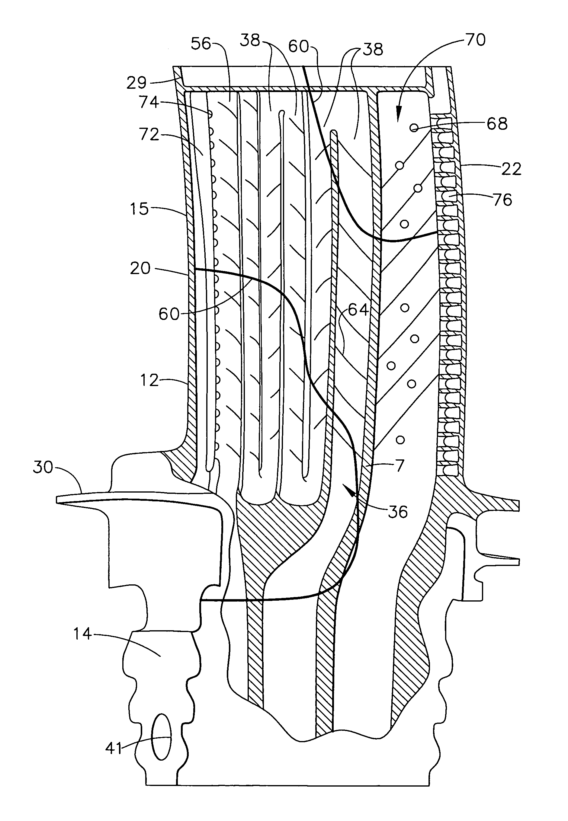
[0009]A gas turbine engine turbine blade includes a hollow airfoil including an airfoil outer wall having transversely spaced apart pressure and suction side walls meeting along chordally spaced apart leading and trailing edges of the airfoil. A radially extending trailing edge cooling air channel within the airfoil includes a bank of pins integral with and extending transversely between the pressure and suction side walls. The pins may be heat transfer pins. The bank of the pins is tuned such that a natural frequency of the blade associated with an engine forced driving mode of the blade is sufficiently away from a steady state engine operating frequency to substantially avoid natural frequency resonance of the blade during steady state engine operation. The number, size, and location of the pins may also be optimized to minimize weight, minimize pressure loss, as well as frequency tune the blade.

Problems solved by technology

Without cooling, turbine blades would rapidly deteriorate.
Diverting any portion of the compressor air from use in the combustor necessarily decreases the overall efficiency of the engine.

Method used


Image

  • Turbine blade frequency tuned pin bank
  • Turbine blade frequency tuned pin bank
  • Turbine blade frequency tuned pin bank

Examples


Embodiment Construction

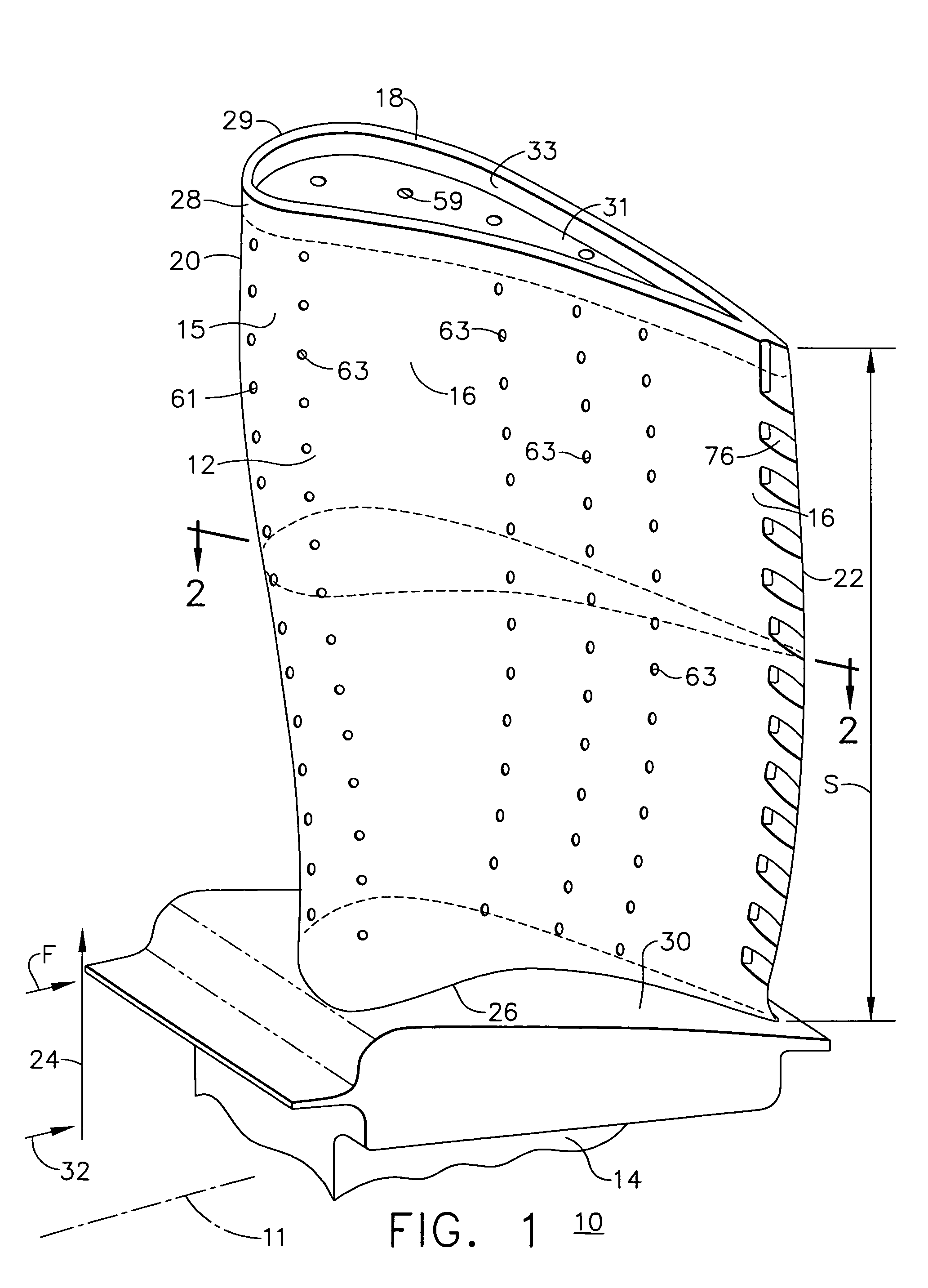
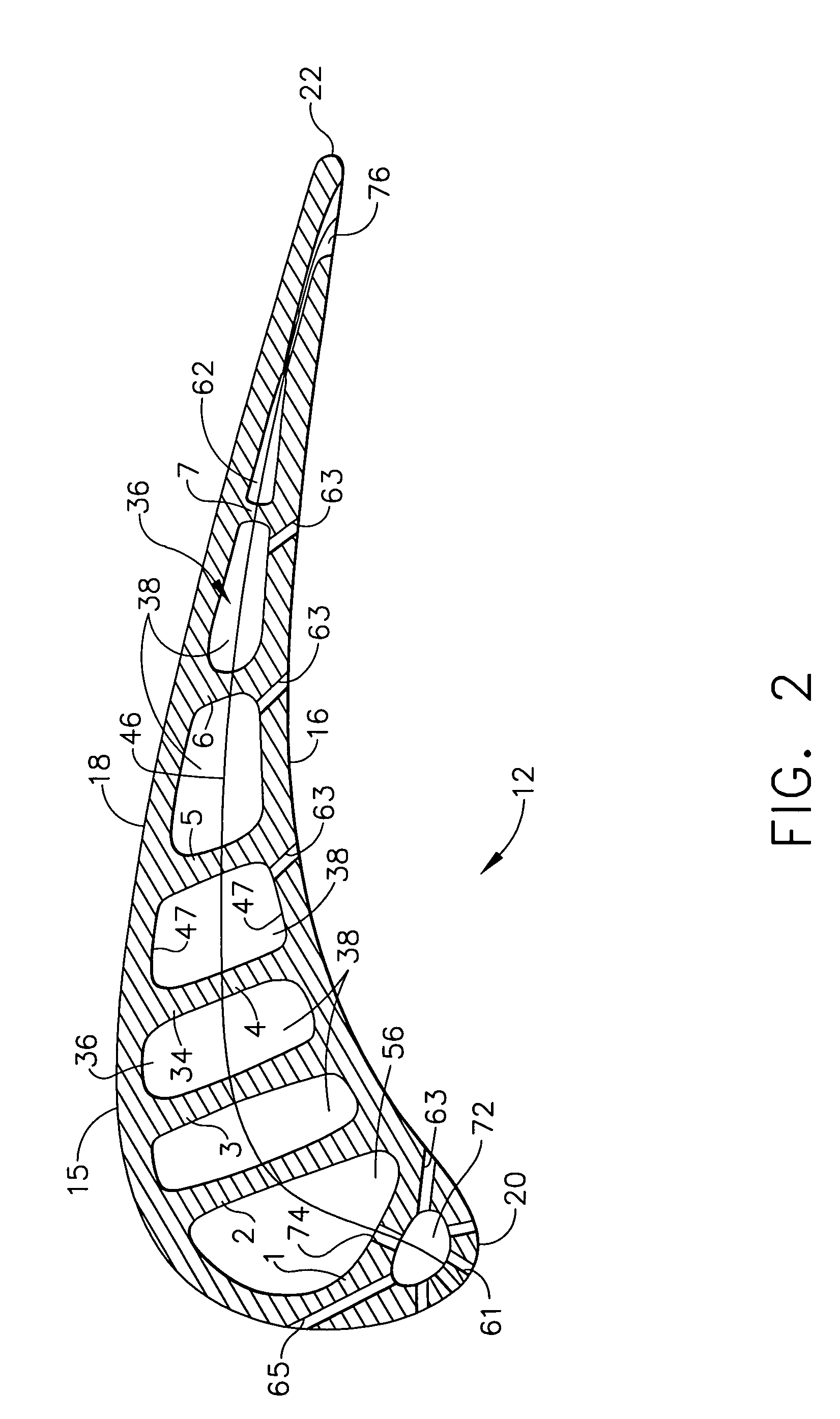
[0017]Illustrated in FIG. 1 is an exemplary turbine blade 10 for a gas turbine engine designed to be operated in a hot gas stream that flows in an axial flow downstream direction F. The blade 10 includes a hollow airfoil 12 extending radially outwardly from a root 14. The root 14 is used to secure the blade 10 to a rotor disk (not shown) of the engine which is circumscribed about an engine centerline 11. As further illustrated in a cross-section of the airfoil 12 in FIG. 2, the airfoil 12 includes an outer wall 15 widthwise or transversely spaced apart pressure and suction side walls 16 and 18, respectively, meeting along an upstream leading edge 20 and a downstream trailing edge 22 which is spaced chordally apart from the leading edge. The airfoil 12 extends radially in a radial direction 24 away from the engine centerline 11 in a spanwise direction of the airfoil 12 from a radially inner base 26 to a radially outer airfoil tip 28 along a span S of the airfoil. The airfoil tip 28 i...


PUM


Abstract

A gas turbine engine turbine blade includes a hollow airfoil extending radially from a blade root to a radially outer airfoil tip. The airfoil includes an airfoil outer wall having transversely spaced apart pressure and suction side walls meeting along chordally spaced apart leading and trailing edges of the airfoil. A radially extending cooling air supply channel within the airfoil includes a bank of pins integral with and extending transversely between the pressure and suction side walls. The bank of the pins is tuned such that a natural frequency of the blade associated with an engine forced driving mode of the blade is sufficiently away from a steady state engine operating frequency to substantially avoid natural frequency resonance of the blade during steady state engine operation. The bank of the pins is tuned by locations of the pins within the cooling air supply channel.

Description

BACKGROUND OF THE INVENTION[0001]1. Field of the Invention[0002]This invention relates to coolable hollow gas turbine engine turbine blades and, more particularly, to pins extending between pressure and suction side walls of the blades.[0003]2. Description of Related Art[0004]Gas turbine engines typically employ a row of coolable hollow turbine blades secured to an outer perimeter of a rotor disk with a stationary turbine nozzle having a plurality of stator vanes disposed upstream therefrom. The combustion gases flow between the stator vanes and between the turbine blades for extracting energy to rotate the rotor disk. The temperatures within gas turbines may exceed 2500 degrees Fahrenheit and cooling of turbine blades is very important in terms of blade longevity. Without cooling, turbine blades would rapidly deteriorate. Cooling for turbine blades is very desirable and much effort has been devoted by those skilled in the blade cooling arts to devise geometries for internal cavitie...

Claims


Application Information

Patent Timeline
Patent Type & Authority Patents(United States)
IPC IPC(8): F01D25/36F01D5/16F01D5/18
CPCF01D5/16Y10S416/50F05D2260/96
Inventor RINCK, GERARD ANTHONYCLARKE, JONATHAN PHILIPSTEGEMILLER, MARK EDWARDSINGH, HARDEVBRASSFIELD, STEVEN ROBERT
Owner GENERAL ELECTRIC CO
Learn More