
Switched-capacitor controller to control the rise times of on-chip generated high voltages

a technology controller, which is applied in the direction of power conversion systems, pulse techniques, instruments, etc., can solve the problems of undue stress on flash eprom memory core cells, and achieve the effect of accurately controlling the rise times of on-chip generated high voltag

Inactive Publication Date: 2006-02-21
MONTEREY RES LLC
View PDF9 Cites 51 Cited by
  • Summary
  • Abstract
  • Description
  • Claims
  • Application Information

AI Technical Summary

Benefits of technology

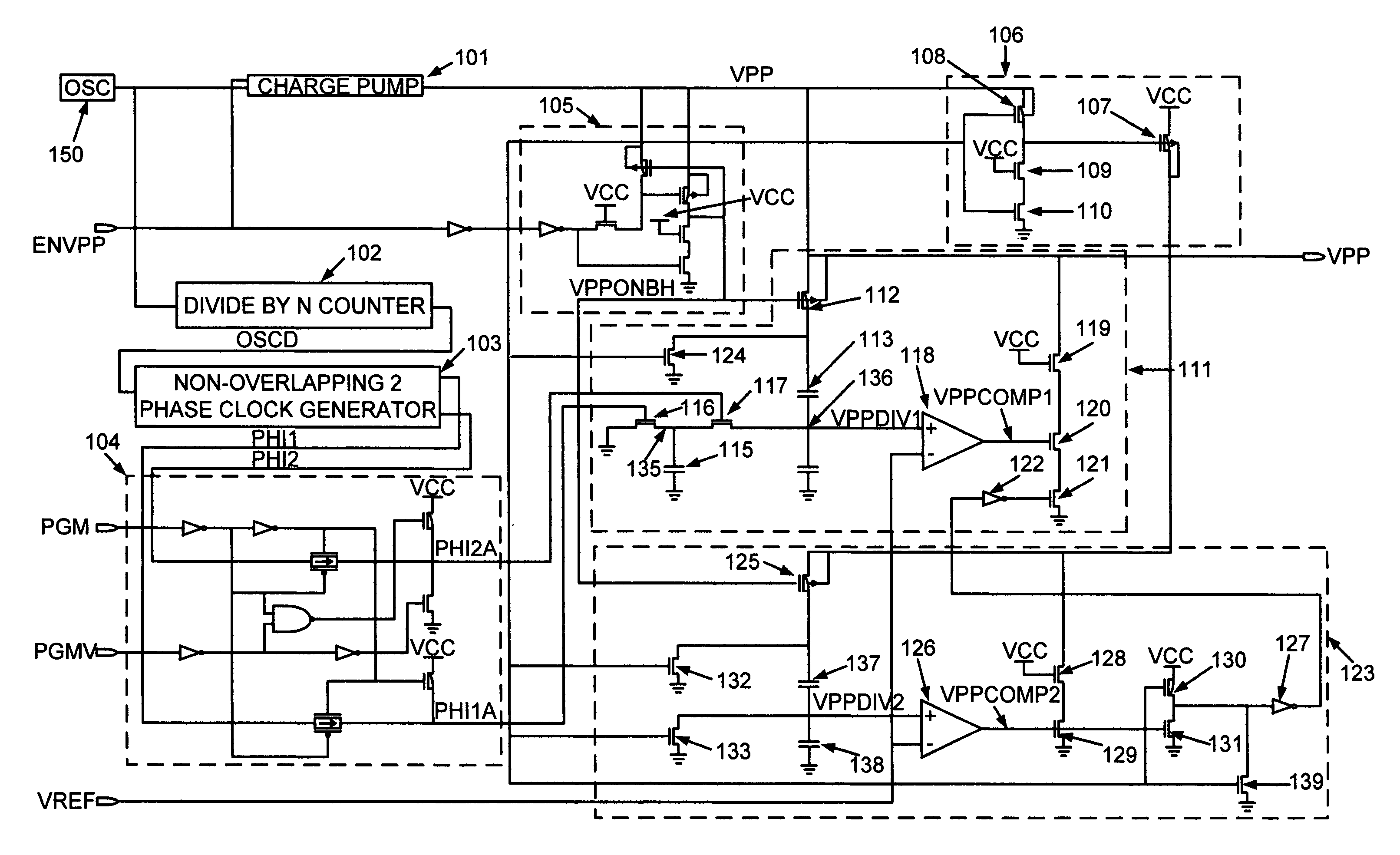
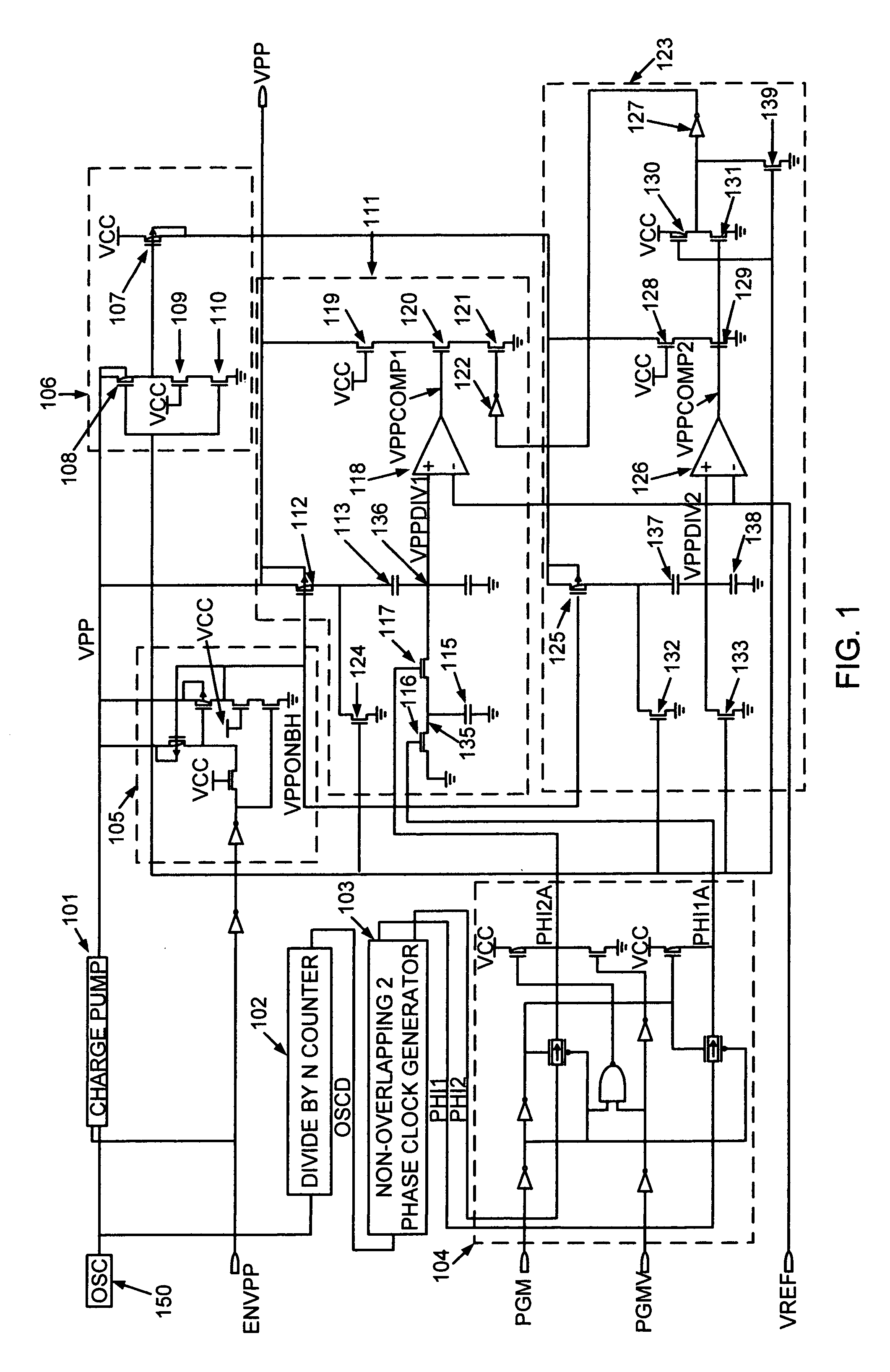
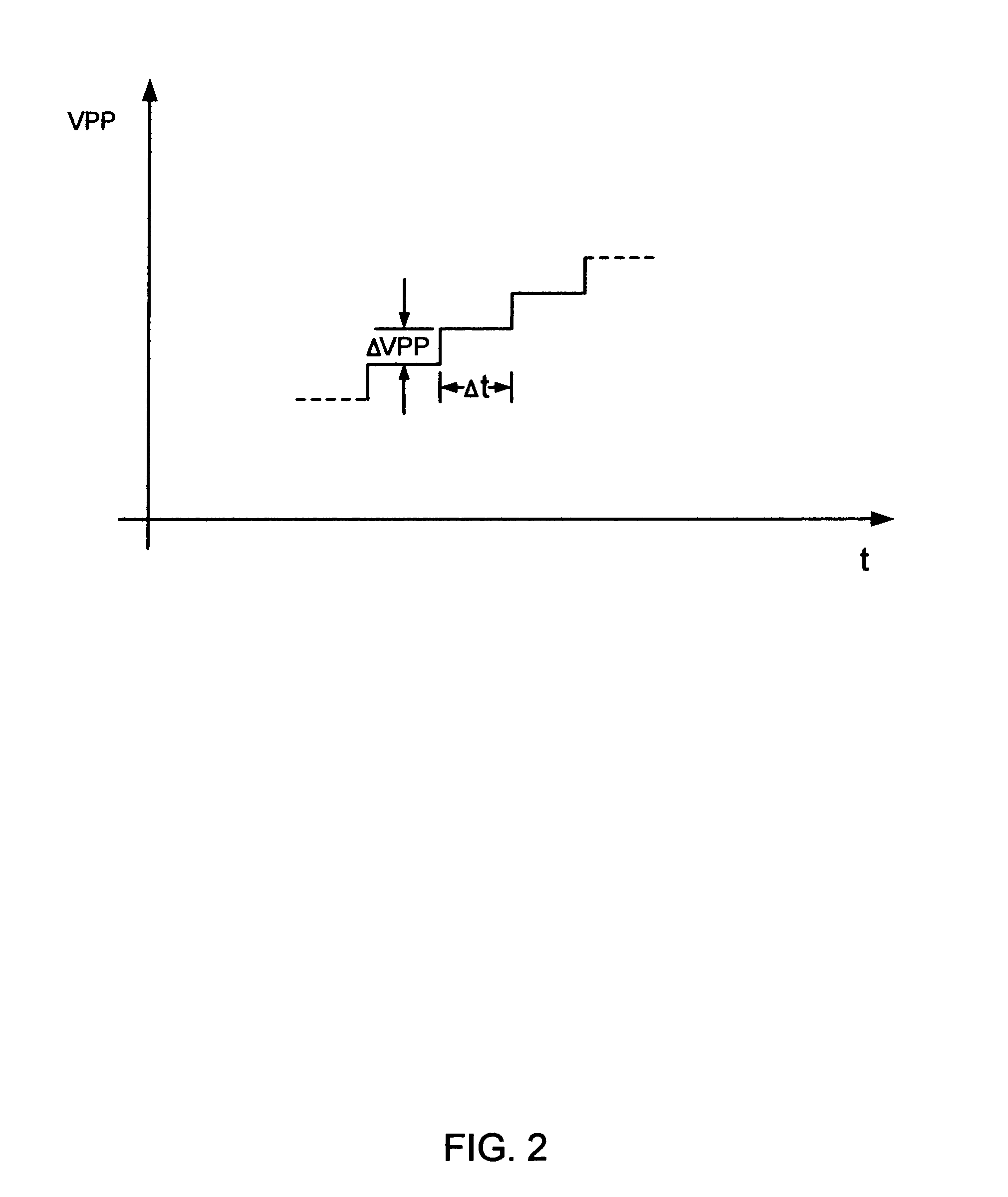
[0005]The present invention pertains to a switched-capacitor circuit for accurately controlling the rise times of on-chip generated high voltages. An on-chip charge pump is used to generate a high voltage (VPP) from an external power supply voltage (VCC). This high voltage signal (VPP) can be used to program Flash memory cells. The capacitor of a switched capacitor circuit is selectively switched between ground and a given node voltage. This produces a stair-stepped ramp function. The period of the steps is controlled according to a clock signal or oscillator. The frequency of this clock signal may be altered to generate the desired period. The voltage increases of the steps is regulated by a reference voltage multiplied by a ratio between two capacitor values. Thereby, the switched capacitor system accurately controls the rise-time of the VPP signal as a function of the frequency of the clock signal and the ratio of the two capacitor values.

Problems solved by technology

This is due to the fact that if the rise time of Vpp were too fast, it may impose undue stress on the flash EPROM memory core cells when the Vpp is applied to the control gate of the cell during channel hot electron programming or programming via Fowler-Nordheim tunneling.

Method used


Image

  • Switched-capacitor controller to control the rise times of on-chip generated high voltages
  • Switched-capacitor controller to control the rise times of on-chip generated high voltages
  • Switched-capacitor controller to control the rise times of on-chip generated high voltages

Examples


Embodiment Construction

[0011]The present invention pertains to a switched-capacitor circuit for controlling the rise times of on-chip generated high voltages. In the following detailed description of the present invention, numerous specific details are set forth in order to provide a thorough understanding of the present invention. However, it will be obvious to one skilled in the art that the present invention may be practiced without these specific details or by using alternate elements or methods. In other instances well known methods, procedures, components, and circuits have not been described in detail as not to unnecessarily obscure aspects of the present invention.

[0012]Referring to FIG. 1, a circuit diagram of the currently preferred embodiment of the present invention is shown. The circuit comprises a charge pump 101. Alternatively, a voltage multiplication circuit may be implemented in place of the charge pump 101. The charge pump 101 is typically comprised of a series of MOS diode connected tr...


PUM


Abstract

A switched capacitor controller accurately controls the rise time of an on-chip generated high voltage. An on-chip charge pump is used to generate a high voltage (VPP) from an external power supply voltage (VCC). This high voltage signal (VPP) can be used to program Flash memory cells. A capacitor of a switched capacitor circuit is selectively switched between ground and a given node voltage. This generates a stair-stepped ramp function. The period of the steps is controlled according to a clock signal. This clock signal may be altered to produce the desired period. The voltage increases of the steps is regulated by a reference voltage multiplied by a ratio between two capacitor values. Thereby, the rise-time of the ramp function is accurately controlled as a function of the frequency of the clock signal and the ratio of the two capacitor values.

Description

TECHNICAL FIELD[0001]The present invention relates to a switched-capacitor circuit for controlling the rise times of on-chip generated high voltages.BACKGROUND ART[0002]Non-volatile memory chips are used in a wide variety of electrical applications, computers, communications devices, consumer electronics, and any other application where data must be retained when power is no longer being supplied. Flash erasable programmable read-only memory (EPROM) chips are non-volatile memory chips which also offer the ability of being programmed and erased. In order to program and erase these flash EPROM chips, high voltages varying from 10 to 16 volts are typically required to perform the programming and erasing operations. These high voltages are commonly referred to as Vpp. The high voltages are usually generated on the flash EPROM chips based on an externally supplied low voltage power suppy (Vcc). Circuitry, such as “charge pumps,” on the flash EPROM chip take the Vcc power supply voltage a...

Claims


Application Information

Patent Timeline
Patent Type & Authority Patents(United States)
IPC IPC(8): H03K4/06
CPCG11C16/12G11C16/30H03K4/023H02M3/07H02M1/36
Inventor CHUNG, MICHAEL S. C.
Owner MONTEREY RES LLC
Learn More