
Indicators for early detection of potential failures due to water exposure of polymer-clad fiberglass

a polymer-clad fiberglass and potential failure technology, applied in the direction of threaded fasteners, bolts, transportation and packaging, etc., can solve the problems of composite insulators being vulnerable to certain failure modes, insulators can suffer mechanical failure of rods, ceramic insulators, etc., and achieve the effect of longer lasting

Inactive Publication Date: 2006-02-21
ELECTRIC POWER RES INST INC
View PDF0 Cites 42 Cited by
  • Summary
  • Abstract
  • Description
  • Claims
  • Application Information

AI Technical Summary

Benefits of technology

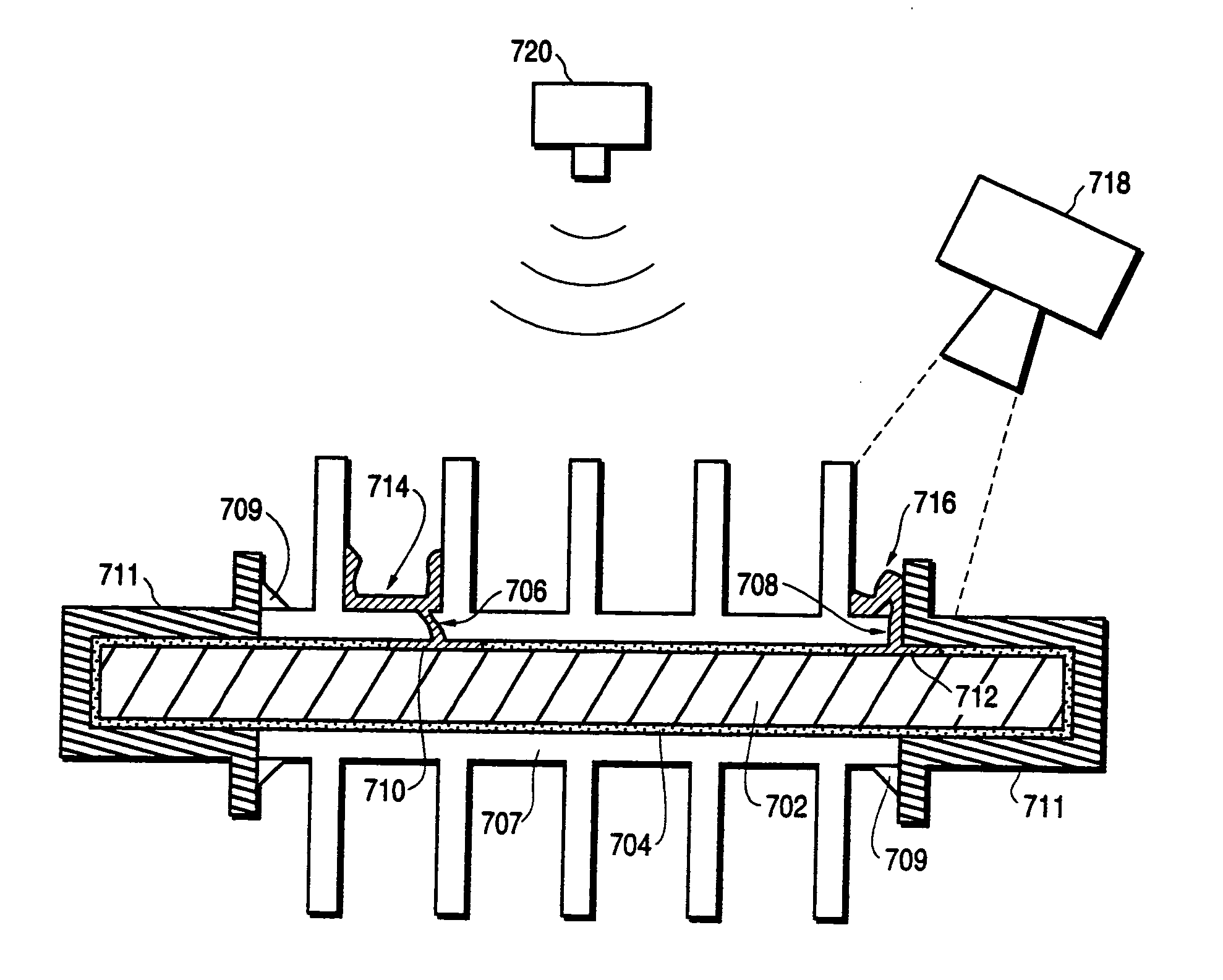
The patent describes a composite insulator that can alert when a rod is exposed to environmental factors that may cause failure. The insulator is made with a fiberglass rod surrounded by a polymer housing and fitted with metal end fittings. It contains a dye-based chemical dopant that is dispersed around the rod and can bond to the insulator components. The dopant is activated when moisture enters the insulator and creates a deposit on the outer surface of the insulator. This deposit can be detected visually or through imaging instruments. The dopant can be an organic dye or a stain that covalently bonds with silicone rubber or a delivery mechanism using Quantum Dots. The technical effect of this invention is to provide an early warning of impending failure of a rod, which can prevent accidents and reduce maintenance costs.

Problems solved by technology

Traditional insulators are made of ceramics, such as glass, but because ceramic insulators are typically heavy and brittle, a number of new insulating materials have been developed.
Although composite insulators exhibit certain advantages over traditional ceramic and glass insulators, such as lighter weight and lower material and installation costs, composite insulators are vulnerable to certain failures modes due to stresses related to environmental or operating conditions.
For example, insulators can suffer mechanical failure of the rod due to overheating or mishandling, or flashover due to contamination.
A significant cause of failure of composite insulators is due to moisture penetrating the polymer insulator housing and coming into contact with the fiberglass rod.
These are: stress corrosion cracking (brittle-fracture), flashunder, and destruction of the rod by discharge activity.
The failure mechanisms associated with brittle fracture are generally attributable to either acid or water leaching of the metallic ions in the glass fibers resulting in stress corrosion cracking.
Flashunder is an electrical failure mode, which typically occurs when moisture comes into contact with the fiberglass rod and tracks up the rod, or the interface between the rod and the insulator housing.
When the moisture, and any by-products of discharge activity due to the moisture, extend a critical distance along the insulator, the insulator can no longer withstand the applied voltage and a flashunder condition occurs.
This is often seen as splitting or puncturing of the insulator rod.
When this happens, the insulator can no longer electrically isolate the electrical conductors from the transmission line structure.
Destruction of the rod by discharge activity is a mechanical failure mode.
In this failure mode, moisture and other contaminants penetrate the weather-shed system and come into contact with the rod, resulting in internal discharge activity.
These internal discharges can destroy the fibers and resin matrix of the rod until the unit is unable to hold the applied load, at which point the rod usually separates.
Because the three main failure modes can mean a loss of mechanical or electrical integrity, such failures can be quite serious when they occur in transmission line insulators.
As stated above, many composite insulator failures have been linked to water ingress into the fiberglass material comprising the insulator rod.
Since all three failure modes—brittle fractures, flashunder, and destruction of the rod by discharge activity, occur in the insulator rod, they are hidden by the housing and cannot easily be seen or perceived through casual inspection.
For example, simple visual inspection of an insulator to detect failure due to moisture ingress requires close-up viewing that can be very time consuming, costly, and generally does not yield a definitive “go” or “no-go” rating.
Additionally, in some cases, detection of rod failure through visual inspection techniques may simply be impossible.
Such tests can be performed some distance from the insulator, but are limited in that only a small number of failure modes can be detected.
The composition of the dye or marker that is used for this type of inspection mechanism, however, is very important due to the environmental conditions that the dye is subjected to, as well as the practical limitations relating to inspection techniques for detecting the presence of the dye.
However, some water-soluble dyes are photosensitive and can fade over time when subjected to outdoor conditions.
In general, silicone rubber is difficult to stain.

Method used


Image

  • Indicators for early detection of potential failures due to water exposure of polymer-clad fiberglass
  • Indicators for early detection of potential failures due to water exposure of polymer-clad fiberglass
  • Indicators for early detection of potential failures due to water exposure of polymer-clad fiberglass

Examples


Embodiment Construction

[0030]A composite insulator or vessel containing an oil soluble chemical dopant for providing early warning of impending failure due to exposure of the fiberglass rod or glass-reinforced resin material to the environment is described. In the following description, for purposes of explanation, numerous specific details are set forth in order to provide a thorough understanding of the present invention. It will be evident, however, to one of ordinary skill in the art, that the present invention may be practiced using variants of these specific details. In other instances, well-known structures and devices are shown in block diagram form to facilitate explanation. The description of preferred embodiments is not intended to limit the scope of the claims appended hereto.

[0031]Lightweight composite insulators were developed in the late 1950s to replace ceramic insulators for use in high capacity (100's of kilovolt) power transmission lines. Such insulators featured great weight reduction,...


PUM

PropertyMeasurementUnit
molar concentrationaaaaaaaaaa
core diameteraaaaaaaaaa
pHaaaaaaaaaa

Abstract

A composite insulator containing means for providing early warning of impending failure due to stress corrosion cracking, flashunder, or destruction of the rod by discharge activity conditions is described. A composite insulator comprising a fiberglass rod surrounded by a polymer housing and connected with metal end fittings on either end of the rod is doped with a dye-based chemical dopant. The dopant is located around the vicinity of the outer surface of the fiberglass rod. The dopant is formulated to possess migration and diffusion characteristics, and to be inert in dry conditions and compatible with the insulator components. The dopant is positioned within the insulator such that upon the penetration of moisture through the housing to the rod through a permeation pathway in the outer surface of the insulator, the dopant will become activated and will leach out of the same permeation pathway or diffuse through the housing. The activated dopant then creates a deposit or stain on the outer surface of the insulator housing. The dopant comprises an oil-soluble dye, an indicator, or a stain compound that can either be visually identified, or is sensitive to radiation at one or more specific wavelengths. The dopant could also be formulated by a nanoparticle enabled material. Deposits of activated dopant on the outer surface of the insulator can be detected upon imaging of the outer surface of the insulator by appropriate imaging instruments or the naked eye.

Description

CROSS-REFERENCE TO RELATED APPLICATIONS[0001]The present application is a Continuation-in-Part application of currently patent application Ser. No. 10 / 641,511, filed on Aug. 14, 2003 now U.S. Pat. No. 6,930,254 and entitled Chemically-Doped Composite Insulator for Early Detection of Potential Failures Due to Exposure of the Fiberglass Rod, which is assigned to the assignees of the present application.FIELD OF THE INVENTION[0002]The present invention relates generally to insulators for power transmission lines, and more specifically to chemically-doped transmission and distribution components, such as composite (non-ceramic) insulators or polymer-clad fiberglass vessels that provide improved identification of units with a high risk of failure due to environmental exposure of the fiberglass core.BACKGROUND OF THE INVENTION[0003]Power transmission and distribution systems include various insulating components that must maintain structural integrity to perform correctly in often extreme...

Claims


Application Information

Patent Timeline
Patent Type & Authority Patents(United States)
IPC IPC(8): H01B17/34H01B17/32H01B17/50
CPCH01B17/50H01B17/325Y10T428/31515
Inventor MITCHELL, JOSEPH N.HABY, SPRING M.RUSHFORTH, DENNIS S.VAN DYKE, MARK E.OVIATT, JR., HENRY W.PHILIPS, ANDREW J.HILL, JR., RALPH H.MARSHALL, MARY C.
Owner ELECTRIC POWER RES INST INC
Learn More