
Process for cooling a product in a heat exchanger employing microchannels

a technology of heat exchanger and product, which is applied in indirect heat exchangers, lighting and heating apparatuses, laminated elements, etc., can solve the problems of reducing the power requirements of compressors used, and achieve the effects of reducing thermal and mass diffusion distances, and reducing the power requirements of compressors

Inactive Publication Date: 2006-02-21
VELOCYS CORPORATION
View PDF137 Cites 70 Cited by
  • Summary
  • Abstract
  • Description
  • Claims
  • Application Information

AI Technical Summary

Benefits of technology

[0006]Aluminum is typically used as a material of construction in conventional cryogenic heat exchangers. Aluminum minimizes heat transfer resistance between fluid streams due to the fact that it is a high thermal conductive material. However, since it is a high thermal conductive material aluminum tends to decrease the effectiveness of the heat exchangers due to axial conduction. This limits the ability to shorten the length of these heat exchangers and thereby reduce the overall pressure drop. An advantage of the present invention is that it is not necessary to use high thermal conductive materials such as aluminum in constructing the heat exchanger used with the inventive process.
[0007]This invention relates to a process for cooling a fluid product in a heat exchanger, the process comprising: flowing a fluid refrigerant through a set of refrigerant microchannels in the heat exchanger; and flowing the product through a set of product microchannels in the heat exchanger, the product flowing through the product microchannels exchanging heat with the refrigerant flowing through the refrigerant microchannels, the product exiting the set of product microchannels being cooler than the product entering the set of product microchannels. The heat exchanger may be a two-stream heat exchanger, a three-stream heat exchanger, or a multi-stream heat exchanger. In one embodiment of the invention, the refrigerant flowing through the refrigerant microchannels comprises a refrigerant flowing through a set of first microchannels in the heat exchanger and another refrigerant flowing through a set of second microchannels in the heat exchanger, the refrigerant flowing through the set of second microchannels having a different composition and / or being at a different temperature and / or pressure than the refrigerant flowing through the set of first microchannels.
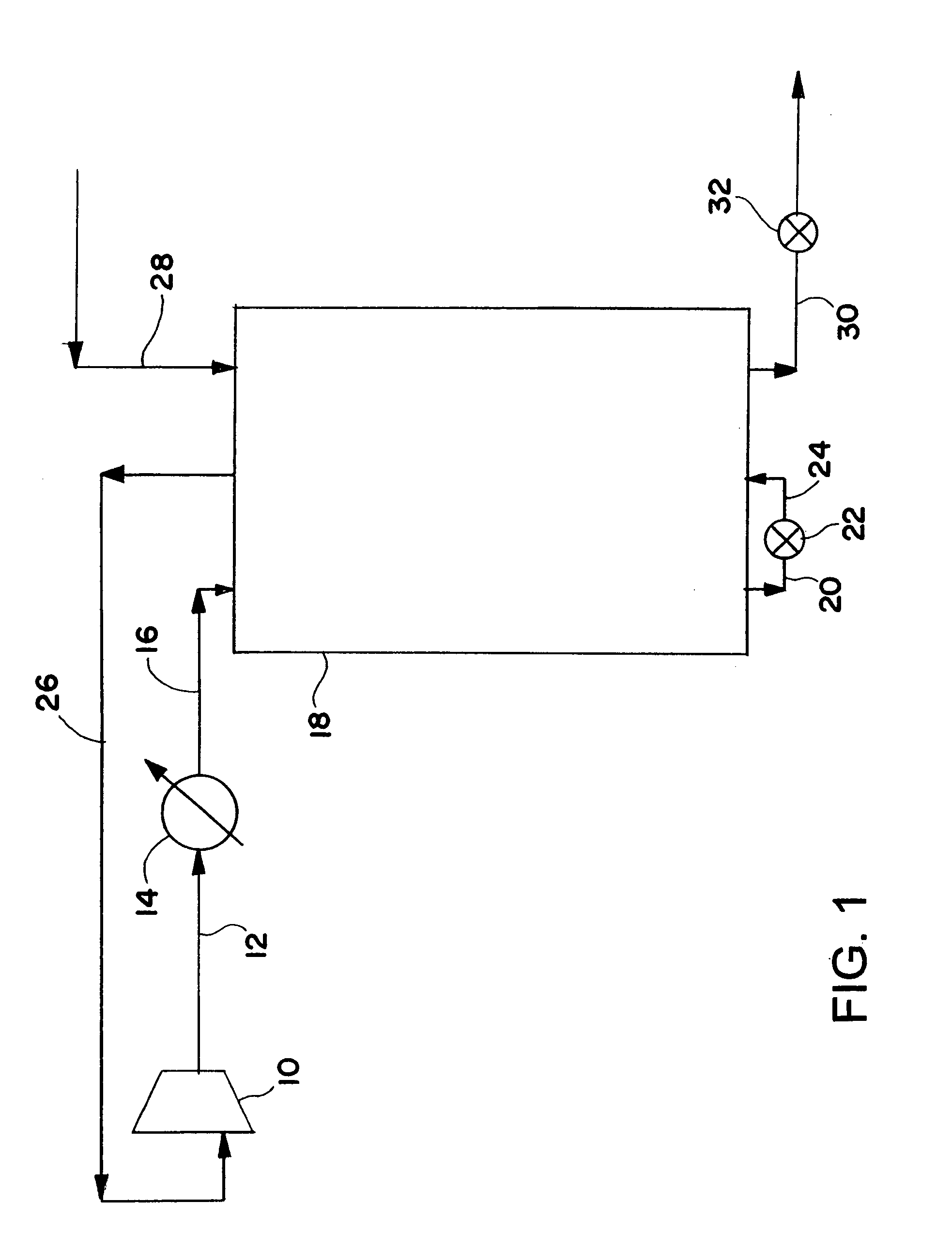
[0008]In one embodiment, the inventive process is operated using non-turbulent flow for the refrigerant flowing through the refrigerant microchannels. Also, in one embodiment, the microchannels may be relatively short, that is, up to about 10 meters in length. This provides for relatively low pressure drops as the refrigerant flows through the microchannels. These relatively low pressure drops reduce the power requirements for compressors used with such processes. For example, in one embodiment of the invention, a reduction in compression ratio of about 18% may be achieved for the inventive process used in making liquefied natural gas as compared to a comparable process not using microchannels for the flow of refrigerant in the heat exchanger.
[0009]Another advantage of the inventive process is that the use of microchannels in the heat exchanger decreases thermal and mass diffusion distances substantially as compared to prior art methods not using microchannels. This allows for substantially greater heat transfer per unit volume of heat exchanger than may be achieved with prior art heat exchangers.

Problems solved by technology

These relatively low pressure drops reduce the power requirements for compressors used with such processes.

Method used


Image

  • Process for cooling a product in a heat exchanger employing microchannels
  • Process for cooling a product in a heat exchanger employing microchannels
  • Process for cooling a product in a heat exchanger employing microchannels

Examples


example 1

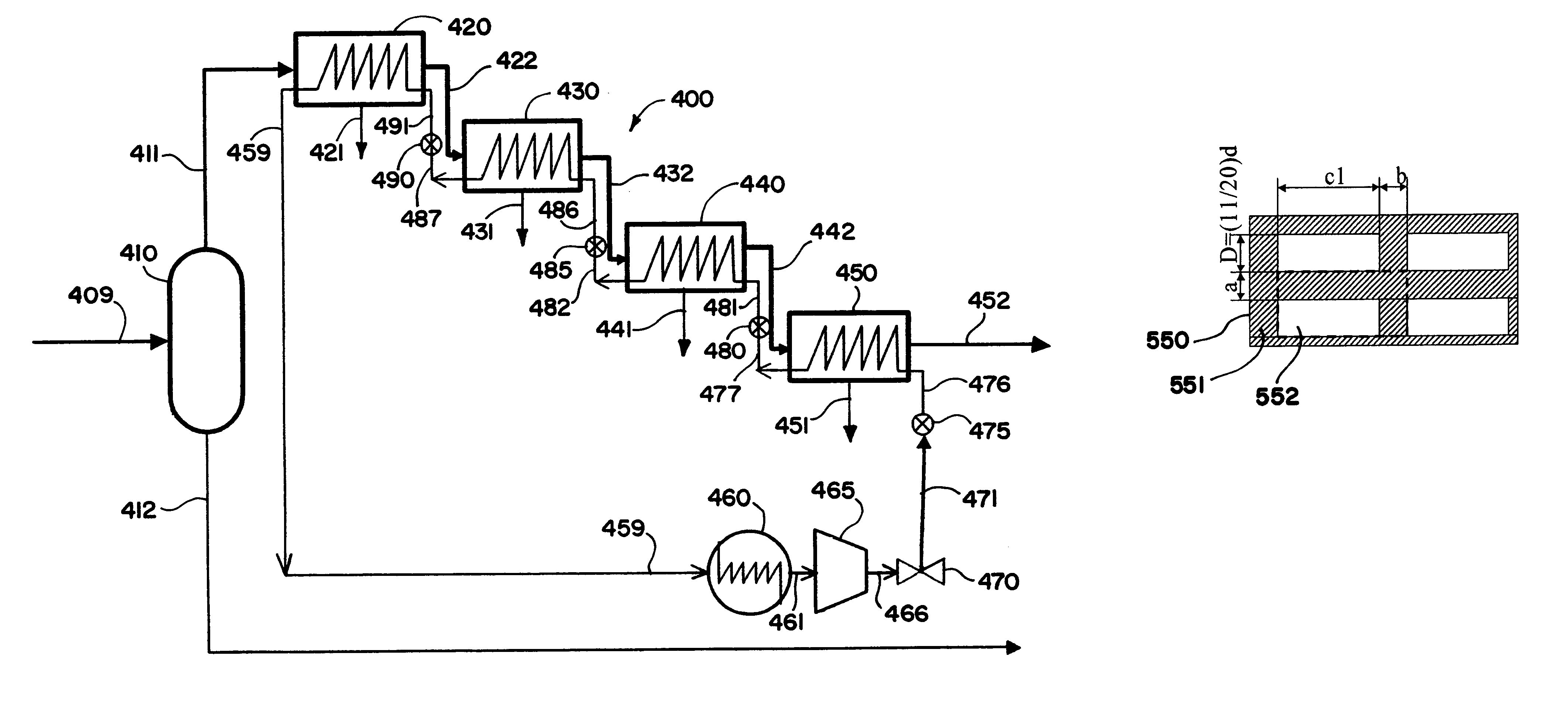
[0097]Natural gas pressure is increased up to 2500 psig and the reduction in refrigerant flow rate (with same operating conditions) to achieve same the outlet temperature of natural gas is estimated. The natural gas pressures are 635, 1000, 1500, 2000, and 2500 psig. As the natural gas pressure is increased, the metal rib thickness between the channels needs to be increased. FIG. 22 shows the metal rib thickness that needs to be changed with natural gas pressure in a representative repeating unit of a heat exchanger. The repeating unit employed in FIG. 22 reads from left to right: natural gas (NG), low pressure refrigerant (LPR), high pressure refrigerant (HPR), LPR, HPR, LPR, NG. The table below gives the values of the metal thickness required at different natural gas pressures. The metal is stainless steel 304.

[0098]

TABLE 1Metal rib thickness at different natural gas pressuresNatural Gaspressure (psig)t1 (in)t2 (in)t3 (in)635.050.073.0101000.064.094.0171500.078.117.0252000.091.138...

example 2

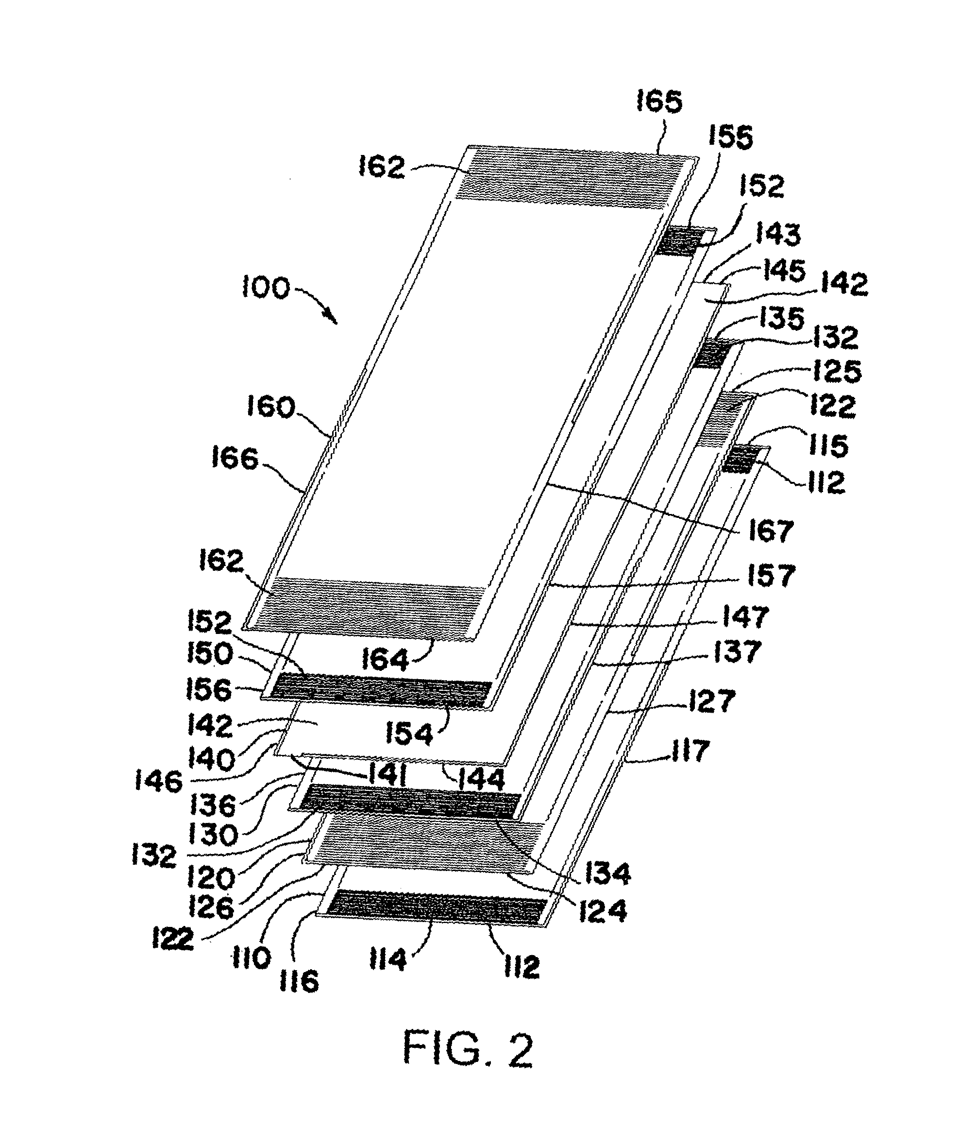
[0104]A three stream heat exchanger is provided for the purpose of liquefying natural gas. Two of the streams involve the flow of a refrigerant through the heat exchanger, and the third stream involves the flow of the natural gas. One of the refrigerant streams is a high pressure refrigerant stream which is operated at a pressure of 323.3–322.8 psig, and the other refrigerant stream is a low pressure refrigerant stream which is operated at a pressure of 29.95–27.75 psig. The high pressure and low pressure refrigerant streams flow counter current to each other as illustrated in FIG. 3 The natural gas stream flows cross current to the refrigerant streams as illustrated in FIG. 3.

[0105]The heat exchanger is constructed of stainless steel (SS 304). It has a length of 1.00 meter, a width of 1.70 meters, and a stacking height of 2.85 meters. The core volume for the heat exchanger is 4.85 cubic meters. Repeating units of microchannel layers corresponding to repeating unit 100 in FIG. 2 are...


PUM


Abstract

This invention relates to a process for cooling or liquefying a fluid product (e.g., natural gas) in a heat exchanger, the process comprising: flowing a fluid refrigerant through a set of refrigerant microchannels in the heat exchanger; and flowing the product through a set of product microchannels in the heat exchanger, the product flowing through the product microchannels exchanging heat with the refrigerant flowing through the refrigerant microchannels, the product exiting the set of product microchannels being cooler than the product entering the set of product microchannels. The process has a wide range of applications, including liquefying natural gas.

Description

[0001]This application is a continuation-in-part of U.S. application Ser. No. 10 / 219,990, filed Aug. 15, 2002, now U.S. Pat 6,622,519. This prior application is incorporated herein by reference.CROSS-REFERENCE TO RELATED APPLICATIONS[0002]The present application is related to the following commonly-assigned applications filed on Aug. 15, 2002: “Integrated Combustion Reactors and Methods of Conducting Simultaneous Endothermic and Exothermic Reaction,” (U.S. application Ser. No. 10 / 222,196); “Multi-Stream Microchannel Device,” (U.S. application Ser. No. 10 / 222,604); and “Process for Conducting an Equilibrium Limited Chemical Reaction in a Single Stage Process Channel,” (U.S. application Ser. No. 10 / 219,956). These applications are incorporated herein by reference.TECHNICAL FIELD[0003]This invention relates to a process for cooling a product in a heat exchanger employing microchannels for the flow of refrigerant and product through the heat exchanger. The process is suitable for liquef...

Claims


Application Information

Patent Timeline
IPC IPC(8): F25J1/00F25J1/02F25J3/00F28D9/00F28F3/04
CPCF25J1/0022F25J1/0052F25J1/0207F25J1/0212F25J1/0262F25J5/002F28D9/0037F28D9/0093F28F3/048F25J1/0276F25J2290/32F28F2260/02F25J2290/20F25J2290/44F28F2250/104
Inventor MATHIAS, JAMES A.ARORA, RAVISIMMONS, WAYNE W.MCDANIEL, JEFFREY S.TONKOVICH, ANNA LEEKRAUSE, WILLIAM A.SILVA, LAURA J.QIU, DONGMING
Owner VELOCYS CORPORATION
Learn More