Seismic structural device

a seismic structural and joint technology, applied in the direction of girders, rod connections, couplings, etc., can solve the problems of joint rotation, and achieve the effects of improving structure dynamic characteristics, softening structure, and prolonging the fundamental period of structur

Inactive Publication Date: 2006-02-21
SKIDMORE OWINGS & MERRILL LLP
View PDF16 Cites 12 Cited by
  • Summary
  • Abstract
  • Description
  • Claims
  • Application Information

AI Technical Summary

Benefits of technology

[0009]The present invention is a “pin-fuse” joint that is generally utilized in a beam-to-column joint assembly. The pin fuse joint is designed to be incorporated into the frame of a building or other structure subject to seismic activity and to improve a structure's dynamic characteristics by allowing the joint to slip under extreme loads. This slippage changes the structures dynamic characteristics by lengthening the structures fundamental period and essentially softening the structure, allowing the structure to exhibit elastic properties during seismic events. By utilizing the pin-fuse joint, it is generally not necessary to use frame members as large as typically used for a similar sized structure to withstand an extreme seismic event, thereby overall building costs can also be reduced through the use of the pin-fuse joint of the present invention.
[0010]The pin-fuse joint is generally employed near the end of a beam, where the beam attaches to the column. Rather than attaching directly to the column, a plate assembly is welded to the column and extends therefrom for attachment to the beam. It is the attachment of the plate assembly to the beam that creates the “pin-fuse” joint. To create the joint, the plate assembly and the end of the beam are designed to mate and be held together by a pipe / pin assembly extending through the web of the beam and through connection plates that extend outward from the plate assembly. Additionally, the end of the plate assembly has a curved flange end connector which abuts against an opposing curved flange end connector located at the end of the beam. The curved flange end connectors of the plate assembly and the beam are then secured together by torqued high-strength steel bolts. These bolted connections allow for the curved flange end connector of the beam to slip relative to the curved flange end connector or the plate assembly when subject to extreme seismic loads without a significant loss in clamping force. Movement in the joint is further restricted by treating the faying surfaces of the curved flange end connectors of the plate assembly and the beam with brass. The brass shims used within the connection possesses a well-defined load-displacement behavior and excellent cyclic attributes.
[0011]The friction developed from the clamping force from the bolted flange end connection and the brass shims against the steel surface of the curved flange end connectors prevent the joint from slipping under most service loading conditions, such as those imposed by wind, gravity, and moderate seismic events. High-strength bolts are torqued to provide a slip resistant connection by developing friction between the connected surfaces. However, under extreme seismic loading conditions, the level of force applied to the curved flange ends exceeds the product of the coefficient of friction times the normal bolt clamping force, which cause the joint to rotate while maintaining connectivity.
[0012]The rotation of the joint during seismic events provides for the transfer of shear forces and bending moment from the structural steel beams to the structural steel columns. This rotation dissipates energy, which is also known as “fusing.” It is this energy dissipation that reduces potential damage to the structure due to seismic activity.
[0013]Although the joints of the present invention will slip under extreme seismic loads to dissipate the energy, the joints will, however, remain elastic due to their construction. Furthermore, no part of the joint becomes plastic or yields when subjected to the loading and the slip. This allows a moment-resisting frame utilizing the joint construction of the present invention to remain in services after enduring a seismic event and conceivably resist further seismic activity.

Problems solved by technology

However, under extreme seismic loading conditions, the level of force applied to the curved flange ends exceeds the product of the coefficient of friction times the normal bolt clamping force, which cause the joint to rotate while maintaining connectivity.

Method used


Image

  • Seismic structural device
  • Seismic structural device
  • Seismic structural device

Examples


Embodiment Construction

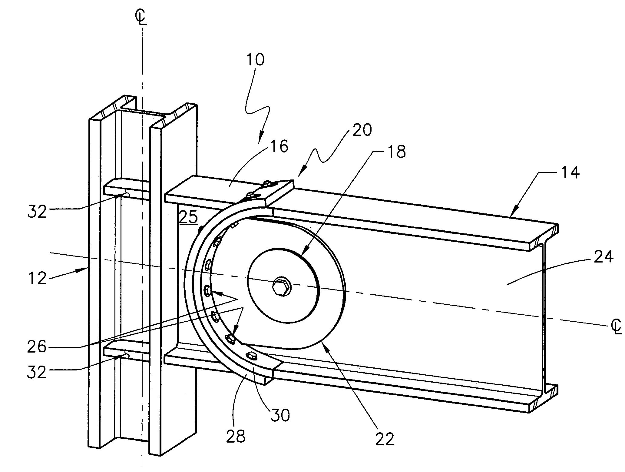
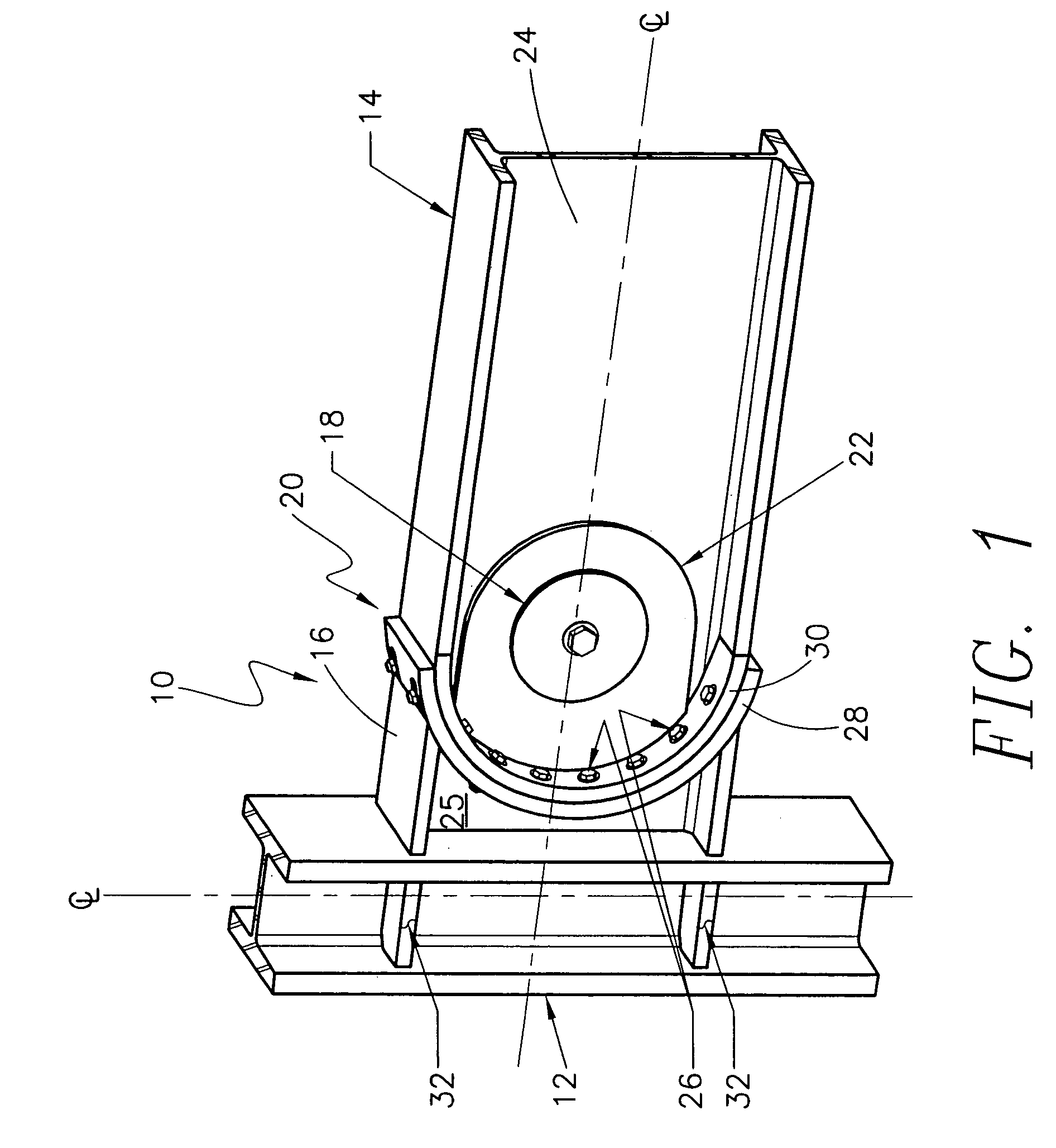
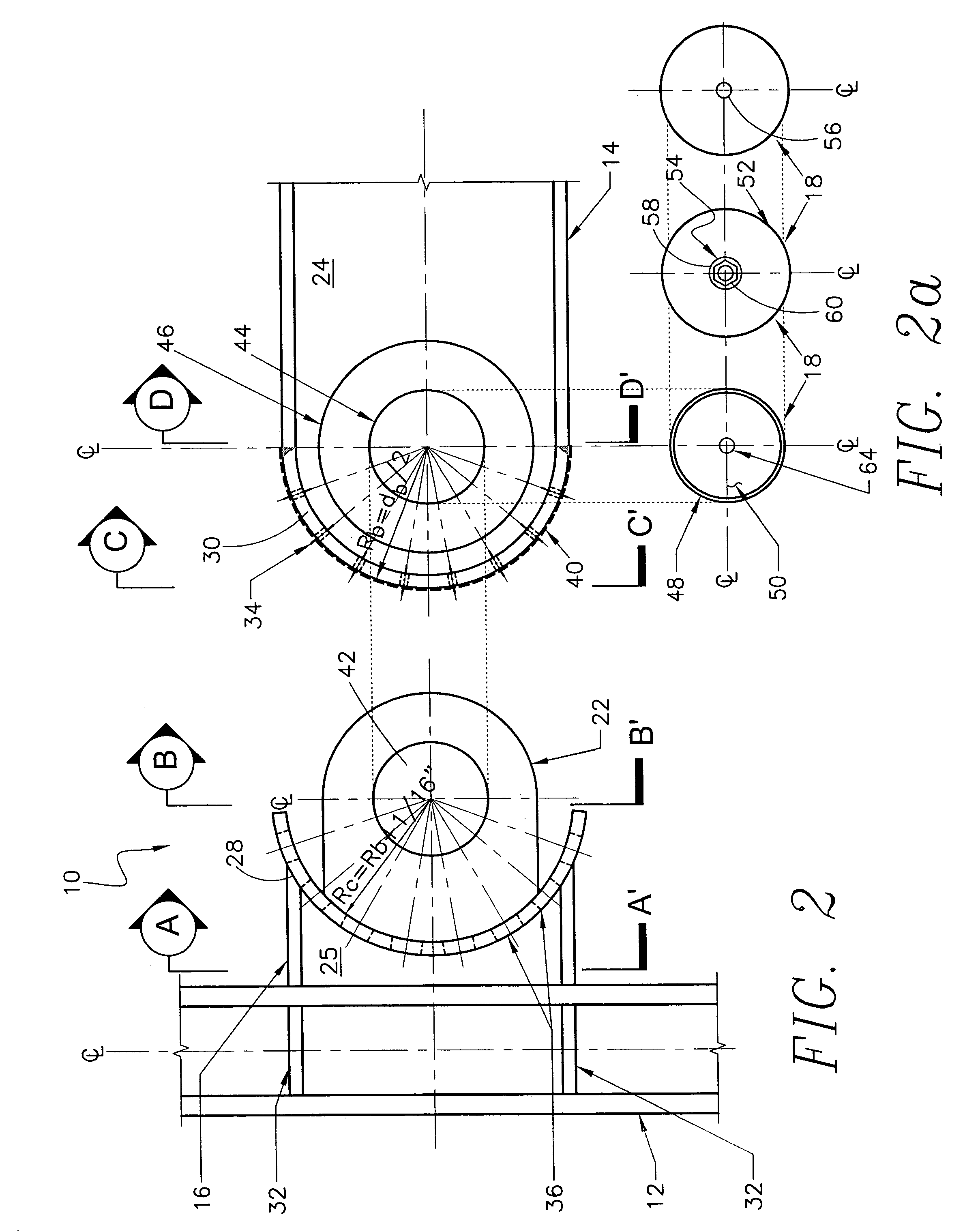
[0027]FIG. 1 is a perspective view of one embodiment of the beam-to-column joint assembly 10 of the present invention. As seen in FIG. 1, the beam-to-column joint assembly 10 consists of a structural steel column 12 attached to a structural steel beam 14 via a steel plate assembly 16 that extends between the column 12 and the beam 14. The steel plate assembly 16 is welded directly to the column 12 and is attached to the beam 14 via a pin-fuse joint 20. To create the pin-fuse joint 20, the plate assembly 16 is connected to the beam 14 via a structural steel pipe or pin 18 that extends through the web 24 of the beam 14 and two twin connection plates 22 extending from the plate assembly 16. Additionally, the opposing ends of both the plate assembly 16 and the beam 14 have curved flange end connectors 28 and 30, respectively, that are designed to abut against with one another when the joint 20 is complete. High-strength bolts 26 then extend through the opposing curved flange end connect...


PUM

PropertyMeasurementUnit
curvatureaaaaaaaaaa
strengthaaaaaaaaaa
slip thresholdaaaaaaaaaa

Abstract

A pin-fuse joint generally utilized in a beam-to-column joint assembly subject to extreme seismic loading is described. The pin-fuse joint resists bending moments and shears generated by these loads. The joint is comprised of standard structural steel building materials, but may be applied to structures comprised of structural steel, reinforced concrete, and or composite materials, e.g., a combination of structural steel and reinforced concrete. The beam-to-column assembly is comprised of a column and a beam and a plate assembly that extends between the column and the beam. The plate assembly is welded to the column and is attached to the beam via the pin-fuse joint. The pin fuse joint is created by a pin connection through the beam and the connection plates of the plate assembly at the web of the beam. Additionally, both the plate assembly and the beam have curved flange end connectors that sit flush against one another separated only by a brass shim when the beam and plate assembly are joined. The curved flange end connectors of the beam and plate assembly are then secured against one another by torqued high-strength bolts.

Description

RELATED APPLICATION DATA[0001]The present application is a divisional of U.S. application Ser. No. 10 / 200,679, filed Jul. 22, 2002, now U.S. Pat. No. 6,681,538 which is incorporated herein by reference to the extent permitted by law.BACKGROUND OF THE INVENTION[0002]1. Field of the Invention[0003]The present invention generally relates to a beam-to-column joint to be utilized in the frame construction of buildings or other structures that are subject to seismic loads. In particular, the beam-to-column joint is a pin-fuse joint designed to lengthen dynamic periods and effectively reduce the forces that must be resisted within the frame so that the frame can withstand seismic activity without sustaining significant damage.[0004]2. Description of the Related Art[0005]Structures have been constructed, and are being constructed daily, in areas subject to extreme seismic activity. Special considerations must be given to the design of such structures. In additional to normal loading conditi...

Claims


Application Information

Patent Timeline
Patent Type & Authority Patents(United States)
IPC IPC(8): B23P11/00E04B1/24E04B1/58E04C3/29E04D13/00E04H9/02
CPCE04B1/2403E04C3/06E04D13/00E04H9/024Y10T29/4984E04B2001/2442E04B2001/2445E04B2001/2448E04B2001/5868E04C2003/0452Y10T403/645Y10T403/32254Y10T403/64Y10T29/49892Y10T29/49947E04B2001/2439F16B2200/50F16B2200/506
Inventor SARKISIAN, MARK P.
Owner SKIDMORE OWINGS & MERRILL LLP
Why Eureka
Try Eureka