Controller for a wire electrical discharge machine
a wire electrical discharge machine and control device technology, applied in the direction of electrical-based machining apparatus, metal-working apparatus, manufacturing tools, etc., can solve the problems of metal particles and bubbles not being discharged properly, affecting the operation of wire vibration, so as to reduce the reduction in machining efficiency due to machining control and stable machining
- Summary
- Abstract
- Description
- Claims
- Application Information
AI Technical Summary
Benefits of technology
Problems solved by technology
Method used
Image
Examples
first embodiment
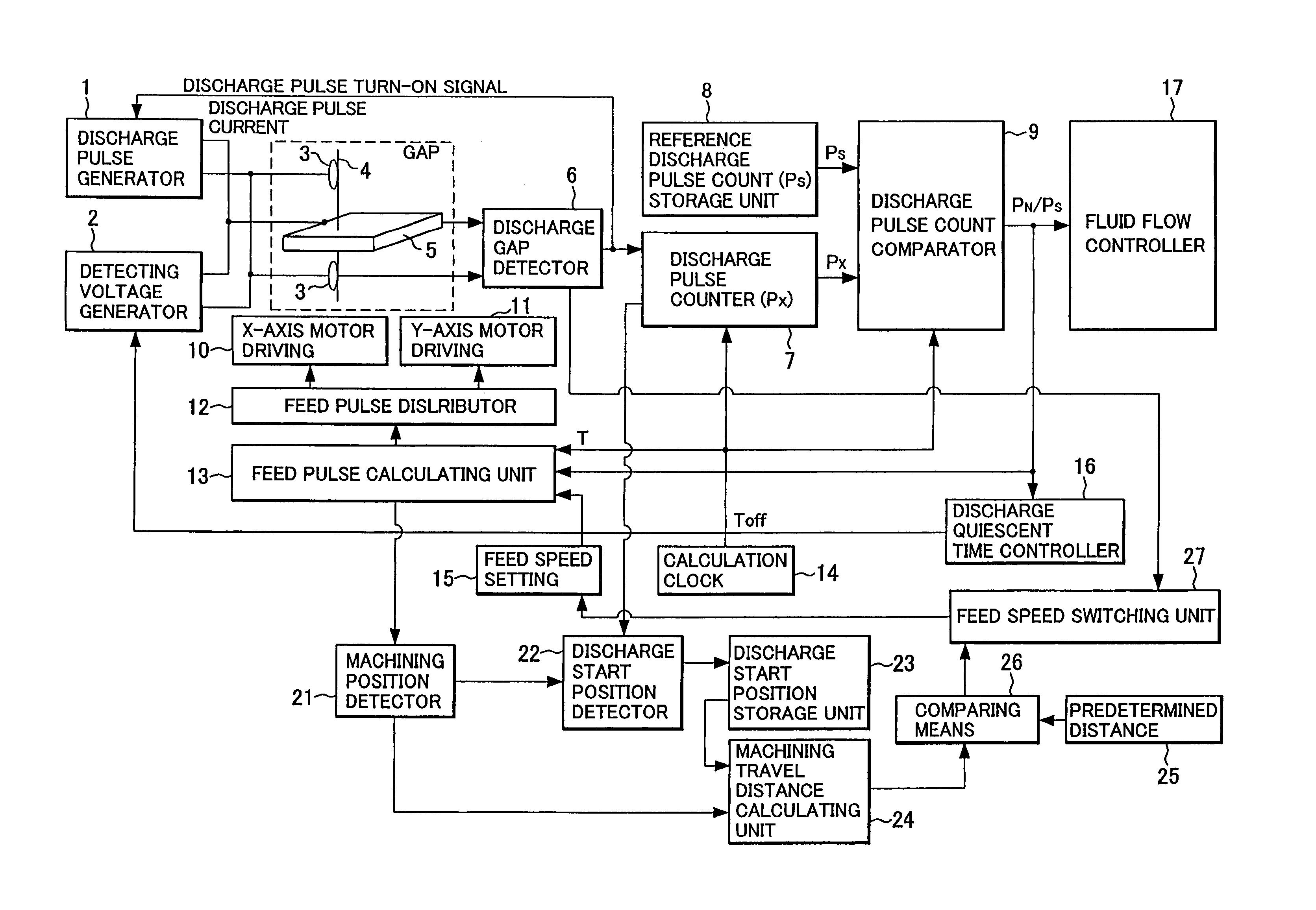
[0114]FIG. 3 is a block diagram illustrating main elements of the controller for a wire electrical discharge machine according to the present invention.
[0115]Reference numeral 1 in FIG. 3 indicates a discharge pulse generator comprising a circuit having transistors and other active elements for generating discharge pulse current, a capacitor charging / discharging circuit, a direct current power supply, etc. One of the outputs from the discharge pulse generator 1 is connected to the workpiece 5 and the other is connected to contact brushes 3 disposed above and below the workpiece 5, supplying pulsed discharge current to a gap between the running wire electrode 4 and workpiece 5.
[0116]Reference numeral 2 indicates a detecting voltage generator comprising a direct current power supply, a circuit having resistors, capacitors, and active elements such as transistors etc. for generating a voltage for detecting the state of the gap, and other components. One of the outputs from the detectin...
second embodiment
[0165]FIG. 8 is a block diagram illustrating main elements of the controller for a wire electrical discharge machine according to the present invention. Only the differences from the first embodiment shown in FIG. 3 will be described below.
[0166]In the second embodiment, instead of counting and storing the number of discharge pulses, the integrated value of discharge pulse current is obtained from a current detecting circuit 18 and a discharge pulse current integrated value calculation and storage unit 37. Further, instead of the reference discharge pulse count storage unit, a reference discharge pulse current integrated value storage unit 38 is provided. Then, ratios used for controlling feed pulses, discharge quiescent time and fluid flow are calculated and outputted by a discharge pulse current integrated value comparator 39.
[0167]More specifically, a reference integrated value of the discharge pulse current is set, instead of the reference number Ps of discharge pulses per unit ...
PUM
| Property | Measurement | Unit |
|---|---|---|
| nozzle radius | aaaaa | aaaaa |
| distance | aaaaa | aaaaa |
| unit time | aaaaa | aaaaa |
Abstract
Description
Claims
Application Information
 - R&D
- Intellectual Property
- Life Sciences
- Materials
- Tech Scout
- Unparalleled Data Quality
- Higher Quality Content
- 60% Fewer Hallucinations
Browse by: Latest US Patents, China's latest patents, Technical Efficacy Thesaurus, Application Domain, Technology Topic, Popular Technical Reports.
© 2025 PatSnap. All rights reserved.Legal|Privacy policy|Modern Slavery Act Transparency Statement|Sitemap|About US| Contact US: help@patsnap.com


